


Appendix A Specifications
PC-LPM-16/PnP User Manual A-6
National Instruments Corporation
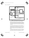
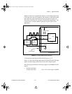
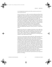
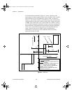
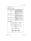
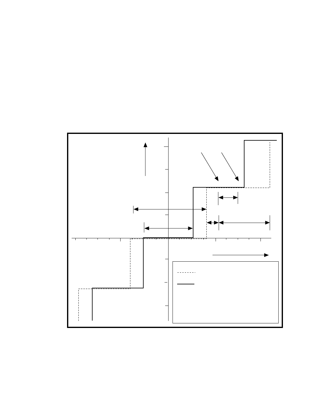
To illustrate these definitions, Figure A-1 shows a portion of the
analog-input-to-digital-output transfer curve for an ideal, ADC overlaid
on the transfer curve of a hypothetical, typical, ADC. As shown in
Figure A-1, the relative accuracy is the deviation of the code transition
voltage from the center of the code for an ideal ADC, expressed in terms
of LSBs. Notice that in this case, an ideal ADC has a relative accuracy
of
±
1/2 LSB, because this definition of relative accuracy encompasses
both nonlinearity and quantization uncertainties. Integral nonlinearity
is the worst case deviation of the center of the code from the ideal
center, expressed in terms of LSBs. Finally, the differential
nonlinearity is deviation of a code width from ideal code width,
expressed in terms of LSBs.
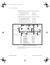
Figure A-1.
ADC Errors
Re1
1
xx
INLe
Re2
2
Output Code (LSB)
-1
1
2
-1
-2
C
ideal
C
actual
V
actual
V
ideal
Practical ADC
analog-input-to-digital-output curve
Ideal ADC
analog-input-to-digital-output curve
C
ideal
= Center of code1 for ideal ADC
C
actual
= Center of code1 for practical ADC
INL error = INLe = C
actual
-C
ideal
Relative Accuracy = Maximum (Rel, Re2)
DNL error = V
actual
-V
ideal
KEY
Input Voltage (LSBs)
a.Book : I.Appendix A Page 6 Wednesday, November 20, 1996 6:36 PM