


Appendix C Using Your PC-LPM-16 (Non-PnP) Board
PC-LPM-16/PnP User Manual C-12
National Instruments Corporation
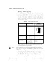
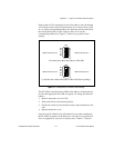
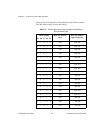
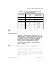
Unipolar Input Selection 2 (0 to 5 V)
Select the unipolar (0 to 5 V) input configuration by using the same
setting as the
±
5 V range setting shown in Figure C-5. You can use this
setting because the ADC is 12-bit. Therefore, 12-bit resolution data is
obtained in both the 0 to +5 V signal range and the 0 to -5 V signal
range while keeping the input configuration for
±
5 V input range. The
jumper configuration for the 0 to 5 V and
±
5 V input signal ranges is
the same. The software handles the distinction between the two ranges.
Installation
You can install the PC-LPM-16 in any available 8-bit or 16-bit
expansion slot in your computer. To optimize the board noise
performance, install the board away from the video card and leave a slot
vacant on each side of the PC-LPM-16, if possible. After you make any
necessary changes with the jumper and switch settings, you are ready to
install the PC-LPM-16.
The following are general installation instructions, but consult your
computer user manual or technical reference manual for specific
instructions and warnings.
1. Turn off and unplug your computer.
2. Remove the top cover or access port to the I/O channel.
3. Remove the expansion slot cover on the back panel of the
computer.
4. Insert the PC-LPM-16 board into any 8-bit or 16-bit slot. It may be
a tight fit, but
do not force
the board into place.
5. Screw the mounting bracket of the PC-LPM-16 board to the back
panel rail of the computer.
6. Replace the cover.
7. Plug in and turn on your computer.
The PC-LPM-16 is installed.