


Appendix D Register-Level Programming
PC-LPM-16/PnP User Manual D-24
National Instruments Corporation
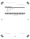
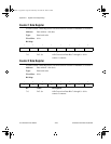
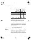
Timer Interrupt Clear Register
Write to the Timer Interrupt Clear Register to clear the interrupt request asserted when a
low pulse is detected on the counter 2 output.
Address: Base address + 06 (hex)
Type: Write-only
Word Size: 8-bit
Bit Map: Not applicable, no bits used.
Digital I/O Register Group
The Digital I/O Register Group contains two registers, the Digital
Output Register and the Digital Input Register. The Digital Output
Register drives the eight digital output lines of the I/O connector. The
Digital Input Register returns the digital state of the eight digital input
lines of the I/O connector.
Bit descriptions for the register in the Digital I/O Register Group
follow.
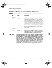
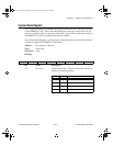
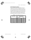
Digital Output Register
Write to the Digital Output Register to control the eight digital output lines of the I/O
connector. The pattern contained in the Digital Output Register is driven onto the eight
digital output lines of the I/O connector.
Address: Base address + 04 (hex)
Type: Write-only
Word Size: 8-bit
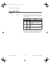
Bit Map:
Bit Name Description
7–0 D<7..0> 8-Bit Output Data 7 through 0—These eight bits
control the digital output lines DOUT 0 through
DOUT 7.
7 6 5 4 3 2 1 0
D7 D6 D5 D4 D3 D2 D1 D0
a.Book : l.Appendix D Page 24 Wednesday, November 20, 1996 6:36 PM