


Chapter 3 Theory of Operation
National Instruments Corporation 3-5 PC-LPM-16/PnP User Manual
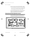
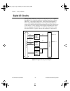
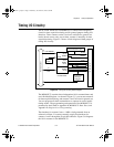
Analog Input Circuitry
The analog input circuitry consists of an input multiplexer, a jumper-
selectable gain stage, and a 12-bit sampling ADC. The 12-bit output is
sign-extended to 16 bits before it is stored in a 256-word deep FIFO
memory.
The input multiplexer stage is made up of a CMOS analog input
multiplexer and has 16 analog input channels (channels 0 through 15).
With the input multiplexer stage, input overvoltage protection of
±
45 V
is available powered on, or
±
35 V powered off.
The PC-LPM-16PnP uses a successive-approximation analog-to-digital
converter (ADC). Software-selectable gains of 0.5, 1, and 2 for the
input signal combined with the ADC’s fixed input range of
±
5 V yield
four useful analog input signal ranges, 0 to 10 V,
±
5 V, 0 to 5 V, and
±
2.5 V.
When an A/D conversion is complete, the ADC clocks the result into
the A/D FIFO. The A/D FIFO is 16 bits wide and 256 words deep. This
FIFO serves as a buffer to the ADC and has two benefits. First, any time
an A/D conversion is complete, the A/D FIFO saves the value for later
reading, and the ADC can start a new conversion. Secondly, the A/D
FIFO can collect up to 256 A/D conversion values before losing any
information, thus giving the software some extra time (256 times the
sample interval) to catch up with the hardware. If the A/D FIFO stores
more than 256 values without the A/D FIFO being read, an error
condition called A/D FIFO Overflow occurs and A/D conversion
information is lost.
The A/D FIFO generates a signal that indicates when it contains
conversion data. You can read the signal state from the PC-LPM-16PnP
Status Register 1.
The output from the ADC is in two’s complement format. In unipolar
input mode (0 to 10 V or 0 to 5 V input range configuration), the data
from the ADC is interpreted as a 12-bit positive number ranging from 0
to 4,095. In bipolar input mode (
±
5 or
±
2.5 V input range
configuration), the data from the ADC is interpreted as a two’s
complement number ranging from -2,048 to +2047. The ADC’s output
is always sign-extended to 16 bits by board circuitry so that data values
read from the FIFO are 16 bits wide.
The ADC on the PC-LPM-16PnP includes calibration circuitry that
makes it possible to minimize zero, full-scale, and linearity errors. The
a.Book : g.chapter 3 Page 5 Wednesday, November 20, 1996 6:36 PM