


Chapter 4 Signal Connections
PC-LPM-16/PnP User Manual 4-10
National Instruments Corporation
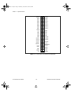
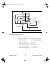
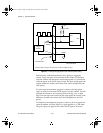
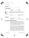
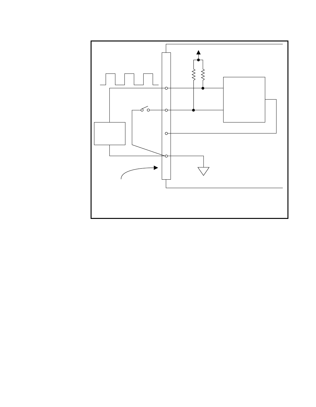
Figure 4-5.
Event-Counting Application with External Switch Gating
Perform pulse-width measurement by level gating to trigger the
counter. Apply the pulse to be measured to the counter GATE input.
Load the counter with the known count and program it to count down
while the signal at the GATE input is high. The pulse width equals the
counter difference (loaded value minus read value) multiplied by the
CLK period.
For time-lapse measurement, program a counter to be edge-gated.
Apply an edge to the counter GATE input to start the counter. You can
program the counter to start counting after receiving a low-to-high
edge. The time lapse since receiving the edge equals the counter value
difference (loaded value minus read value) multiplied by the CLK
period.
For frequency measurement, program a counter to be level-gated and
count the number of falling edges in a signal applied to a CLK input.
The gate signal you apply to the counter GATE input is of known
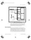
4.7 kW
Signal
Source
Debounced
Switch*
19 DGND
Counter
OUT
CLK
GATE
+5 V
I/O Connector
PC-LPM-16PnP
*Complex switch circuitry is not shown here in order to simplify the figure.
a.Book : h.chapter 4 Page 10 Wednesday, November 20, 1996 6:36 PM