


Appendix D Register-Level Programming
National Instruments Corporation D-7 PC-LPM-16/PnP User Manual
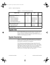
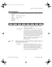
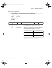
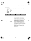
Command Register 2
Command Register 2 contains only one bit that enables the auto-calibration operation of
the ADC.
Address:
Base address + 07 (hex)
Type:
Read-and-write
Word Size:
8-bit
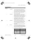
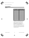
Bit Map:
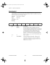
Bit Name Description
7–3 0 Reserved bits—These bits must be set to zero for
future board compatibility.
2 SCANORDER Scan Order Bit—If this bit is cleared, the scan order is
from the channel in Command Register 1 MA<3..0>
to channel 0. The power-on value is 0. If this bit is set,
the scan order begins with channel 0 and ends with the
channel number in MA<3..0>. This bit is cleared upon
power up. To ensure proper scanning, this bit should
be correctly programmed before writing to the
SCANEN* and Channel Selection bits in Command
Register 1. This bit is only present on the
PC-LPM-16PnP.
Note:
The UP function is not yet supported by NI-DAQ. NI-DAQ will support the
UP function in a future release.
1 DISABDAQ Disable Data Acquisition Bit—This bit is used to
disable the data acquisition operation. The power-on
value is 0. Upon startup, this bit is cleared and, as a
result, the data acquisition operation is enabled.
Writing a one to this bit disables both A/D conversion
source signals OUT0* and EXTCONV*.
7
6 5 4 3 2 1 0
0 0 0 0 0 SCANORDER DISABDAQ CALEN
a.Book : l.Appendix D Page 7 Wednesday, November 20, 1996 6:36 PM