


Appendix C Using Your PC-LPM-16 (Non-PnP) Board
PC-LPM-16/PnP User Manual C-4
National Instruments Corporation
Configuration and Installation of the
PC-LPM-16 (non-PnP)
Board Configuration
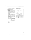
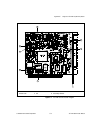
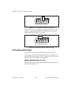
The PC-LPM-16 contains three jumpers and one DIP switch to
configure the PC bus interface and analog input settings. Use the DIP
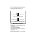
switch to set the base I/O address. Jumper W3 selects the interrupt level.
Jumpers W1 and W2 configure the analog input circuitry. The DIP
switch and jumpers are shown in the parts locator diagram in
Figure C-1.
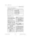
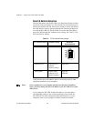
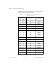
The PC-LPM-16 is factory-configured to a base I/O address of hex 260
and to interrupt level 5. These settings (shown in Table C-1) are suitable
for most systems. However, if your system has other hardware at this
base I/O address or interrupt level, you need to change these settings on
the PC-LPM-16 (as described in the following pages) or on the other
hardware. Record your settings in the
Hardware and Software
Configuration Form
in Appendix E,
Customer Communication
.