


Appendix D Register-Level Programming
PC-LPM-16/PnP User Manual D-2
National Instruments Corporation
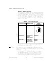
Register Size
The PC-LPM-16/PnP registers are 8-bit registers. To transfer 16-bit
data, you need two consecutive I/O read or write operations. For
example, to read the 16-bit A/D conversion result, read the low byte of
FIFO first, then the high byte of FIFO.
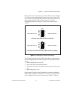
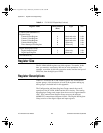
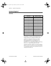
Register Descriptions
Table D-1 divides the PC-LPM-16/PnP registers into four different
register groups. A bit description of each of the registers making up
these groups is included later in this appendix.
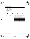
The Configuration and Status Register Group controls the overall
operation of the PC-LPM-16/PnP and the D/A circuitry. The Analog
Input Register Group reads output from the successive-approximation
ADC. The Counter/Timer Register Group accesses the onboard
MSM82C53 counter/timer integrated circuit. The Digital I/O Register
Group consists of the digital output and input registers.
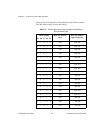
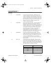
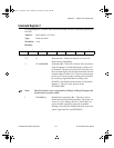
Counter/Timer (MSM82C53)
Register Group
Counter 0 Data Register
Counter 1 Data Register
Counter 2 Data Register
Counter Mode Register
Timer Interrupt Clear Register
8
9
A
B
6
Read-and-write
Read-and-write
Read-and-write
Write-only
Write-only
8-bit
8-bit
8-bit
8-bit
8-bit
Digital I/O Register Group
Digital Output Register
Digital Input Register
4
5
Write-only
Read-only
8-bit
8-bit
*PC-LPM-16PnP only.
Table D-1.
PC-LPM-16/PnP Register Map (Continued)
Register Name
Offset Address
(Hex)
Type Size
a.Book : l.Appendix D Page 2 Wednesday, November 20, 1996 6:36 PM