


Chapter 4 Signal Connections
National Instruments Corporation 4-9 PC-LPM-16/PnP User Manual
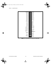
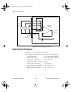
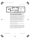
Figure 4-4.
EXTCONV* Signal Timing
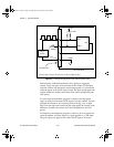
General-Purpose Timing Signal Connections and
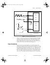
General-Purpose Counter Timing Signals
The general-purpose timing signals include the GATE, CLK, and OUT
signals for the three MSM82C53 counters, except CLK of counter 0 is
not available on the I/O connector. You can use the counter/timers for
general-purpose applications such as pulse and square wave generation,
event counting, and pulse-width, time-lapse, and frequency
measurement. For these applications, user signals sent from the I/O
connector on the CLK and GATE pins go to the counters, and the
counters are user-programmable for various operations. The single
exception is counter 0, which has an internal 1 MHz clock.
Chapter 3,
Theory of Operation
, briefly describes the MSM82C53
counter/timer. For detailed information on this counter/timer, see
Appendix B,
MSM82C53 Data Sheet
.
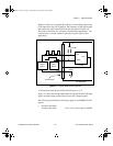
For pulse and square wave generation, program a counter to generate a
timing signal at its OUT output pin.
For event counting, program a counter to count the rising or falling
edges applied to any of the MSM82C53 CLK inputs. You can then read
the counter value to determine the number of edges that have occurred.
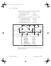
You can gate the counter operation on and off during event counting.
Figure 4-5 shows connections for a typical event-counting operation
where a switch is used to gate the counter on and off.
t
w
200 ns min
V
IL
V
IH
t
w
EXTCONV*
t
int
t
int
20 µs min
(A/D interval)
A/D Conversion Starts within 800 ns of this Edge
a.Book : h.chapter 4 Page 9 Wednesday, November 20, 1996 6:36 PM