


Appendix D Register-Level Programming
PC-LPM-16/PnP User Manual D-4
National Instruments Corporation
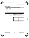
Command Register 1
Command Register 1 indicates the input channel to be read and the interrupt enable bits.
Address:
Base address + 00 (hex)
Type:
Write-only
Word Size:
8-bit
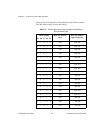
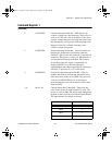
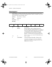
Bit Map:
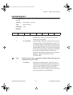
Bit Name Description
7 SCANEN* Scan Enable Bit—This bit enables or disables
multichannel scanning during data acquisition. The
power-on value is 1. If this bit is cleared, analog
channels MA<3..0> through 0 are sampled
alternately. If this bit is set, a single analog channel
selected by MA<3..0> is sampled during the entire
data acquisition operation. In order to perform single-
channel sampling, the UP/DOWN bit in Command
Register 2 must be clear before setting SCANEN* to
1. To set up a scanning mode, two consecutive
writings of this register are necessary. First, write the
desired valve to the UP/DOWN bit in Command
Register 2 if the UP/DOWN bit is not currently set to
its proper value. Then write MA<3..0> with
SCANEN* set to load the scan counter. Then write
MA<3..0> with SCANEN* cleared to enable
scanning.
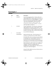
For example, if the UP/DOWN bit is 0 and MA<3..0>
is 0011 and SCANEN* is first set, then cleared, analog
input channels 3 through 0 are sampled alternately
during subsequent data conversions. If SCANEN* is
set and is not cleared (with MA<3..0> still set to
0011), only analog input channel 3 is sampled during
the subsequent data conversions.
See the
Programming Multiple A/D Conversions with
Channel Scanning
section later in this appendix for
more information.
7
6 5 4 3 2 1 0
SCANEN* CNTINTEN EXTINTEN FIFOINTEN MA3 MA2 MA1 MA0
a.Book : l.Appendix D Page 4 Wednesday, November 20, 1996 6:36 PM