


Chapter 3 Theory of Operation
PC-LPM-16/PnP User Manual 3-8
National Instruments Corporation
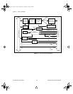
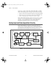
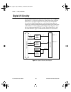
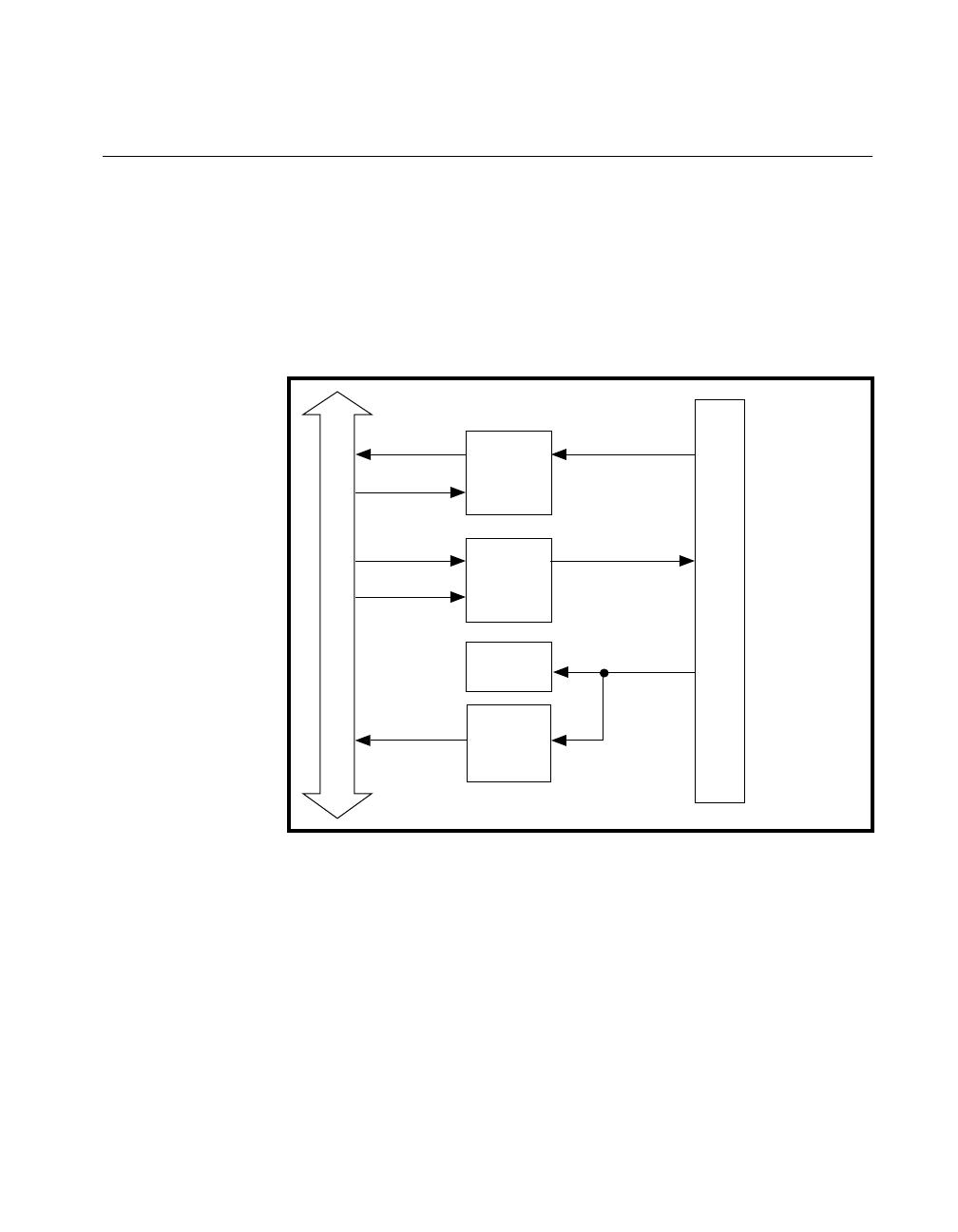
Digital I/O Circuitry
The PC-LPM-16PnP has 16 digital I/O lines that are TTL-compatible.
Pins DIN<0..7> of the I/O connector are digital input lines, and pins
DOUT<0..7> are digital output lines. These lines are monitored or
driven by the Digital Input Register or the Digital Output Register,
respectively. Reading the Digital Input Register returns the current state
of the DIN<0..7> lines. Writing to the Digital Output Register drives
the new value onto the DOUT<0..7> lines. The external device may
drive the EXTINT* signal to indicate the readiness of data transfer.
Figure 3-4.
Digital I/O Circuitry Block Diagram
PC I/O Channel
8
/
8
/
I/O Connector
EXTINT*
8
/
8
/
I/O RD
I/O WR
DIN <0..7>
DOUT<0..7>
Digital
Input
Register
Digital
Output
Register
Status
Register 1
Plug and
Play
Interrupt
Interface
a.Book : g.chapter 3 Page 8 Wednesday, November 20, 1996 6:36 PM