


Appendix D Register-Level Programming
National Instruments Corporation D-5 PC-LPM-16/PnP User Manual
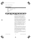
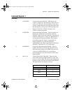
Command Register 1
(Continued)
6 CNTINTEN Counter Interrupt Enable Bit—With this bit, the
counter 2 output can cause interrupts. The power-on
value is 0. If this bit is set, an interrupt occurs when
counter 2 output makes a low-to-high transition. Clear
this interrupt by writing to the Timer Interrupt Clear
Register. If this bit is cleared, interrupts from
counter 2 output are ignored.
5 EXTINTEN External Interrupt Enable Bit—This bit enables and
disables the generation of an interrupt when the
EXTINT* signal on the I/O connector is asserted low
externally. The power-on value is 0. When this bit is
set, the external interrupt is enabled. The external
device that asserts this signal is responsible for
keeping EXTINT* low until the interrupt is
acknowledged, and is then responsible for releasing it.
EXTINT* is pulled up to +5 V on the board.
4 FIFOINTEN First In First Out Interrupt Enable Bit—This bit
enables and disables the interrupt generation when
A/D conversion results are available. The power-on
value is 0. If FIFOINTEN is set, an interrupt is
generated whenever an A/D conversion can be read
from the FIFO.
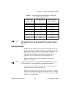
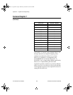
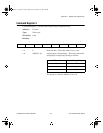
3–0 MA<3..0> Channel Select Bits 3 through 0—These four bits
select which of the 16 input channels are read. The
power-on value is 0000. The analog input multiplexer
depends on these four bits to select the input channel.
The input channel is selected as follows:
MA<3..0>
Selected Channel
0000
0
0001 1
0010 2
0011 3
a.Book : l.Appendix D Page 5 Wednesday, November 20, 1996 6:36 PM