


Chapter 3 Theory of Operation
PC-LPM-16/PnP User Manual 3-10
National Instruments Corporation
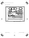
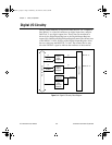
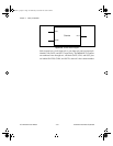
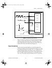
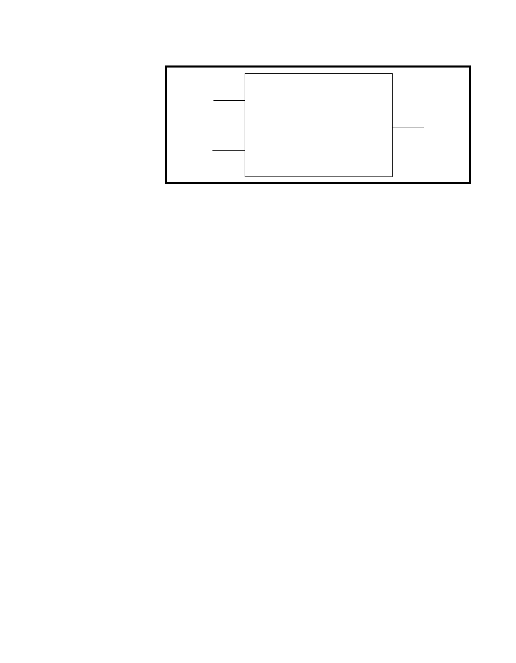
Figure 3-6.
Counter Block Diagram
Each counter has a clock input pin, a gate input pin, and an output pin
labeled CLK, GATE, and OUT, respectively. The MSM82C53 counters
are numbered zero through two, and their GATE, CLK, and OUT pins
are labeled GATE
N
, CLK
N
, and OUT
N
, where
N
is the counter number.
Counter
CLK
GATE
OUT
a.Book : g.chapter 3 Page 10 Wednesday, November 20, 1996 6:36 PM