


Chapter 4 Signal Connections
National Instruments Corporation 4-11 PC-LPM-16/PnP User Manual
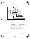
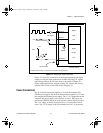
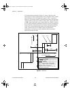
duration. In this case, program the counter to count falling edges at the
CLK input while the gate is applied. The frequency of the input signal
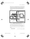
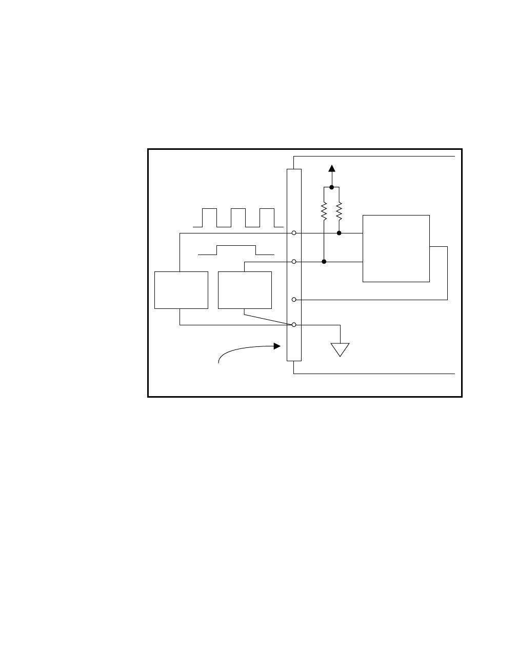
then equals the count value divided by the gate period. Figure 4-6
shows the connections for a frequency measurement application. You
could also use a second counter to generate the gate signal in this
application.
Figure 4-6.
Frequency Measurement Application
4.7 k
Ω
resistors pull up the GATE and CLK pins to +5 V.
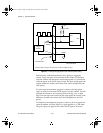
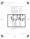
Figure 4-7 shows the timing requirements for the GATE and CLK input
signals and the timing specifications for the OUT output signals.
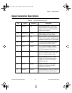
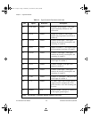
The following specifications and ratings apply to the MSM82C53 I/O
signals:
• Absolute maximum
voltage input rating -0.5 to 7.0 V with respect to DGND
Signal
Source
17
DGND
Counter
OUT
CLK
GATE
+5 V
4.7 kW
I/O Connector
PC-LPM-16PnP
Gate
Source
a.Book : h.chapter 4 Page 11 Wednesday, November 20, 1996 6:36 PM