


Appendix C Using Your PC-LPM-16 (Non-PnP) Board
PC-LPM-16/PnP User Manual C-6
National Instruments Corporation
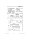
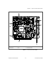
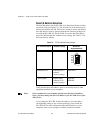
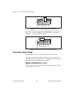
Base I/O Address Selection
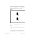
The base I/O address for the PC-LPM-16 is determined by the switches
at position U26 (see Figure C-2). The switches are set at the factory for
the base I/O address hex 260. This factory setting is used as the default
base I/O address value by National Instruments software packages for
use with the PC-LPM-16. The PC-LPM-16 uses the base I/O address
space hex 260 through 26F with the factory setting. See Table C-2 for
the board factory settings.
Verify that this base I/O address space is not already used by other
equipment installed in your computer.
Note:
If any equipment in your computer already uses this base I/O address
space, you must change the base I/O address of the PC-LPM-16 or of the
other device.
If you change the PC-LPM-16 base I/O address, you must make a
corresponding change to any software packages you use with the
PC-LPM-16. For more information about the I/O address of your
computer, refer to your computer’s technical reference manual.
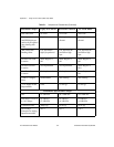
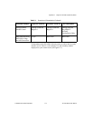
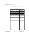
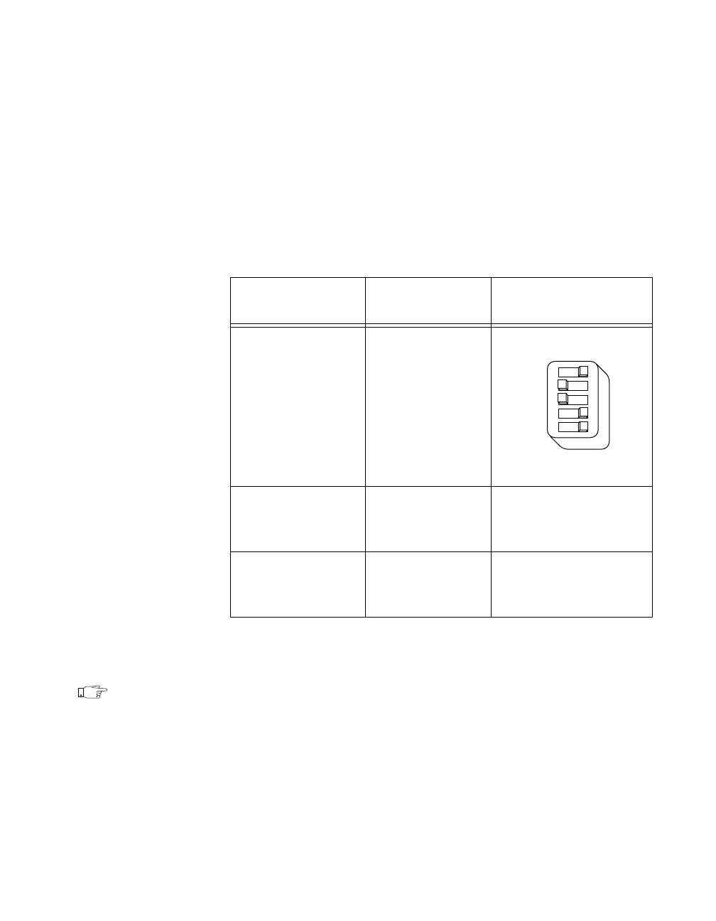
Table C-2.
PC Bus Interface Factory Settings
PC-LPM-16 Board
Default Settings Hardware
Implementation
Base I/O Address
Hex 260
Interrupt Level Interrupt level 5
selected
(factory setting)
W3:
Row 5
Analog Input Bipolar input
selected (
±
5 V)
(factory setting)
W1:
B-C
W2:
B-C
U26
A9
A8
A7
A6
A5