


Chapter 4 Signal Connections
PC-LPM-16/PnP User Manual 4-4
National Instruments Corporation
40
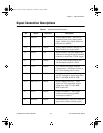
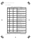
EXTCONV* DGND External Convert Signal—This input
signal externally initiates an A/D
conversion.
41 OUT0 DGND Output of Counter 0—This signal
outputs the programmed waveform of
counter 0.
42 GATE0 DGND Counter 0 Gate Input—This signal
controls the starting, interruption, and
restarting of counter 0.
43 OUT1 DGND Output of Counter 1—This signal outputs
the programmed waveform of counter 1.
44 GATE1 DGND Counter 1 Gate Input—This signal
controls the starting, interruption, and
restarting of counter 1.
45 CLK1 DGND Counter 1 Clock Input—This pin is the
clock input for counter 1.
46 OUT2 DGND Counter 2 Output—This pin is the
output of counter 2.
47 GATE2 DGND Counter 2 Gate Input—This signal
controls the starting, interruption, and
restarting of counter 2.
48 CLK2 DGND Counter 2 Clock Input—This pin is the
clock input for counter 2.
49 +5 V DGND +5 Volts—This is the +5 VDC power
supply from the computer bus. This
power line has a 1.0 A self-resetting fuse
in series.
50 DGND N/A Digital Ground—This pin is connected
to the digital ground signal.
Note:
An asterisk (*) indicates that the signal is active low
.
Table 4-1.
Signal Connection Descriptions (Continued)
Pin
Signal Reference Description
a.Book : h.chapter 4 Page 4 Wednesday, November 20, 1996 6:36 PM