


Appendix D Register-Level Programming
National Instruments Corporation D-3 PC-LPM-16/PnP User Manual
Register Description Format
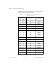
The remainder of this appendix discusses each of the PC-LPM-16/PnP
registers in the order shown in Table D-1. Each register group is
introduced, followed by an individual register description. The
individual register description includes the address, type, word size, and
bit map of the register.
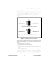
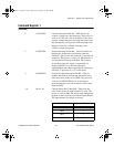
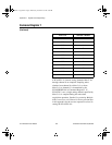
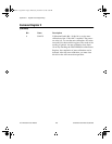
The register bit map shows a diagram of the register with the MSB (bit 7
for an 8-bit register) shown on the left, and the LSB (bit 0) shown on
the right. Each bit is represented by a square with the bit name inside.
An asterisk (*) after the bit name indicates that the bit is inverted
(negative logic).
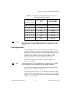
In many of the registers, several bits are labeled with an
X
, indicating
don’t care
bits. When reading a register, these bits may appear set or
cleared, but should be ignored because they have no significance. When
writing to a register, setting or clearing these bit locations has no effect
on the PC-LPM-16PnP hardware. Take special note of the bits labeled
reserved for future use
. The board may not function if you don’t write
the designated value to these register bits.
The bit map field for some write-only registers states
not applicable, no
bits used
. Writing to these registers causes an event to occur on the
PC-LPM-16PnP, such as clearing the analog input circuitry. The data is
ignored when writing to these registers; therefore, any bit pattern will
suffice.
For a detailed bit description of each register concerning the
MSM82C53 chip on the PC-LPM-16/PnP, refer to Appendix B,
MSM82C53 Data Sheet
.
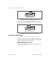
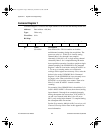
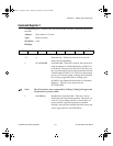
Configuration and Status Register Group
The three registers making up the Configuration and Status Register
Group allow general control and monitoring of the PC-LPM-16/PnP
A/D circuitry. Command Register 1 and Command Register 2 contain
bits that control the operation modes of the A/D circuitry and enable or
disable the interrupt operations. Command Register 3 sets the board
input range. The Status Register reports the A/D conversion status, A/D
conversion error, and the interrupt status.
Bit descriptions for the registers in the Configuration and Status
Register Group are given on the following pages.
a.Book : l.Appendix D Page 3 Wednesday, November 20, 1996 6:36 PM