


Appendix C Using Your PC-LPM-16 (Non-PnP) Board
PC-LPM-16/PnP User Manual C-10
National Instruments Corporation
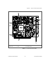
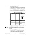
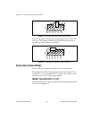
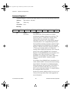
Figure C-3.
Interrupt Jumper Setting IRQ5 (Factory Setting)
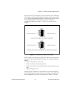
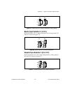
If you do not want to use interrupts, set the jumper on W3 as shown in
Figure C-4. This setting disables the PC-LPM-16 from asserting an
interrupt line on the computer I/O channel.
Figure C-4.
Interrupt Jumper Setting for Disabling Interrupts
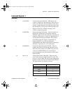
Analog Input Jumper Settings
The PC-LPM-16 is factory-configured for the
±
5 V input range.
Four ranges are available for analog input: bipolar
±
5 V, bipolar
±
2.5 V,
unipolar 0 to 10 V, and unipolar 0 to 5 V. Jumpers W1 and W2 control
the input range for all 16 analog input channels.
Bipolar Input Selection 1 (
±
5 V)
Select the bipolar (
±
5 V) input configuration by setting jumpers W1 and
W2 as shown in Figure C-5.
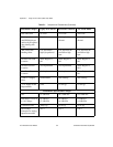
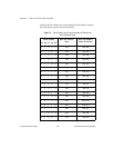
IRQ3
IRQ4
IRQ5
IRQ6
IRQ7
IRQ9
W3
W2
W3
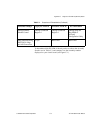
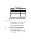
IRQ3
IRQ4
IRQ5
IRQ6
IRQ7
IRQ9
W2