


Chapter 4 Signal Connections
National Instruments Corporation 4-5 PC-LPM-16/PnP User Manual
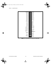
The connector pins can be grouped into categories of analog input
signal pins, digital I/O signal pins, and timing I/O signal pins. Signal
connection guidelines for each of these groups follow.
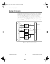
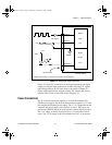
Analog Input Signal Connections
Pins 3 through 18 are analog input signal pins for the ADC. Pins 1 and 2
are analog common signals. You can use these pins for a general analog
power ground tie to the PC-LPM-16PnP. Pins 3 through 18 are tied to
the 16 single-ended analog input channels of the input multiplexer
through 4.7 k
Ω
series resistors. These resistors limit input current to the
multiplexer. Pin 40 triggers conversions slightly after this signal makes
a low-to-high transition. You can only use this pin to cause conversions,
not as a monitor to detect conversions caused by the onboard sample-
interval timer. Refer to Figure 4-4 for more information about
EXTCONV* timing.
The following input ranges and maximum ratings apply to inputs
ACH<0..15>:
Input signal range Bipolar input:
±
5 V or
±
2.5 V
Unipolar input: 0 to 10 V
or 0 to 5 V
Maximum input voltage rating
±
45 V powered on
±
35 V powered off
Warning:
Exceeding the input signal range, even on unused analog input channels,
distorts other input signals. Exceeding the maximum input voltage rating
can damage your board and the computer. National Instruments is
NOT
liable for any damages resulting from such signal connections.
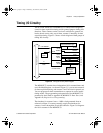
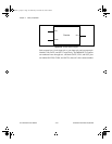
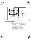
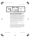
Connections for Signal Sources
Figure 4-2 shows how to connect a signal source to your
PC-LPM-16PnP. When you connect grounded signal sources, carefully
observe the polarity to avoid shorting the signal source output.
a.Book : h.chapter 4 Page 5 Wednesday, November 20, 1996 6:36 PM