


National Instruments Corporation 4-1 PC-LPM-16/PnP User Manual
Signal Connections
Chapter
4
This chapter describes how to make input and output signal connections
to your PC-LPM-16PnP board via the I/O connector.
I/O Connector
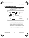
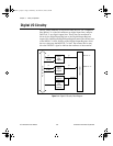
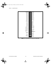
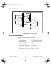
Figure 4-1 shows the pin assignments for the PC-LPM-16PnP
I/O connector. This connector is located on the back panel of the board
and is accessible from the back of your computer after you have
properly installed the board. Installation instructions are in Chapter 2,
Installation and Configuration
.
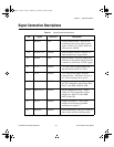
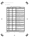
Warning:
Connections that exceed any of the maximum ratings of input or output
signals on the PC-LPM-16PnP can damage the board and the computer.
This includes connecting any power signals to ground and vice versa. Each
signal description in this section includes information about maximum
input ratings. National Instruments is
NOT
liable for any damages resulting
from any such signal connections.
a.Book : h.chapter 4 Page 1 Wednesday, November 20, 1996 6:36 PM