


Chapter 3 Theory of Operation
PC-LPM-16/PnP User Manual 3-4
National Instruments Corporation
request lines available: IRQ3, IRQ4, IRQ5, IRQ6, IRQ7, and IRQ9.
The PC-LPM-16PnP generates interrupts in three different situations:
• When an A/D conversion generates data that can be read from FIFO
• When an active low-level signal is detected on the EXTINT* line
• When a rising-edge signal is detected on counter 2 output
The PC-LPM-16PnP individually enables and clears each one of these
interrupts. For more detailed information on generating interrupts
externally, see the EXTINTEN bit of the Command Register 1
description in Appendix D,
Register-Level Programming
.
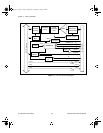
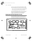
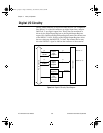
Analog Input and Data Acquisition Circuitry
The PC-LPM-16PnP has 16 channels of analog input with 12-bit
A/D conversion. Using the timing circuitry, the PC-LPM-16PnP can
also automatically time multiple A/D conversions. Figure 3-3 shows a
block diagram of the analog input and data acquisition circuitry.
Figure 3-3.
Analog Input and Data Acquisition Circuitry Block Diagram
CLK0
1 MHz
I/O Connector
A/D
Data
16
Buffer
EXTCONV*
4
ACH<0..15>
A/D RD
MSM82C53
OUT0
256-Word
FIFO
8
PC I/O
Channel
Interface
12-Bit
Sampling
ADC
Input Mux
16-Channel
Single-Ended
Interrupt
Interface
CONVAVAIL
PC I/O Channel
Scanning Counter
A/D Timing
a.Book : g.chapter 3 Page 4 Wednesday, November 20, 1996 6:36 PM