


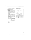
Appendix C Using Your PC-LPM-16 (Non-PnP) Board
PC-LPM-16/PnP User Manual C-8
National Instruments Corporation
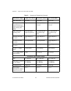
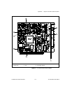
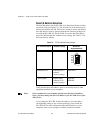
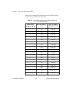
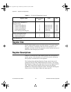
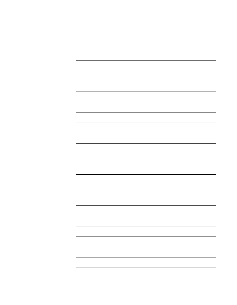
possible switch settings, the corresponding base I/O address, and the
base I/O address space used for that setting.
Table C-3.
Switch Settings with Corresponding Base I/O Address and
Base I/O Address Space
Switch Setting
Base I/O Address
(hex)
Base I/O Address
Space Used (hex)
A9 A8 A7 A6 A5
0
1 0 0 0 100 100–10F
0 1 0 0 1 120 120–13F
0 1 0 1 0 140 140–14F
0 1 0 1 1 160 160–16F
0 1 1 0 0 180 180–18F
0 1 1 0 1 1A0 1A0–1AF
0 1 1 1 0 1C0 1C0–1CF
0 1 1 1 1 1E0 1E0–1EF
1 0 0 0 0 200 200–20F
1 0 0 0 1 220 220–22F
1 0 0 1 0 240 240–24F
1 0 0 1 1 260 260–26F
1 0 1 0 0 280 280–28F
1 0 1 0 1 2A0 2A0–2AF
1 0 1 1 0 2C0 2C0–2CF
1 0 1 1 1 2E0 2E0–2EF
1 1 0 0 0 300 300–30F
1 1 0 0 1 320 320–32F