


Chapter 4 Signal Connections
National Instruments Corporation 4-3 PC-LPM-16/PnP User Manual
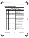
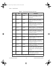
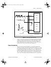
Signal Connection Descriptions
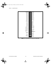
Table 4-1.
Signal Connection Descriptions
Pin
Signal Reference Description
1–2
AIGND N/A Analog Input Ground—The pins are
connected to the analog input ground
signal. ACH<0..15> signals should be
referenced to AIGND.
3–18 ACH<0..15> AGND Analog Input Channels 0 through 15—
These channels are single-ended.
19 DGND N/A Digital Ground—This pin supplies the
reference for the digital signals at the I/O
connector as well as the +5 VDC supply.
20 -12 V DGND -12 VDC Power Supply Output Pin—
The maximum current is 5.0 mA.
21 +12 V DGND +12 VDC Power Supply from the
Computer Bus—This power line has a
0.5 A self-resetting fuse in series.
22–29 DIN<0..7> DGND Digital Input Data Lines—These signals
are TTL-compatible, digital input lines.
DIN7 is the MSB, DIN0 the LSB.
30–37 DOUT<0..7> DGND Digital Output Data Lines—These
signals are TTL-compatible, digital
output lines. DOUT7 is the MSB,
DOUT0 the LSB.
38 OUT1* DGND Output of Counter 1—This signal
outputs the inverted programmed
waveform of counter 1.
39 EXTINT* DGND External Interrupt—This pin is used for
input of the external interrupt signal.
a.Book : h.chapter 4 Page 3 Wednesday, November 20, 1996 6:36 PM