


ND-71548 (E) CHAPTER 3
Page 91
Issue 2
INSTALLATION PROCEDURE
5. INSTALLATION OF CPR
This section explains how to install the CPR into the LPM (MGC). Perform the following procedure for each CPR.
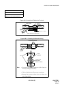
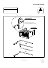
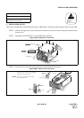
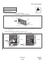
STEP 1: Remove the eight screws from the top cover and the two screws from the front panel, then lift away
the top cover.
STEP 2: Disconnect the SW PWR CA-A from PWR SW connector.
Figure 009-4 Removal of Top Cover
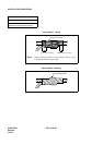
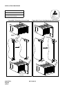
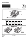
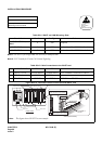
STEP 3: Remove the two screws from the front panel, then detach the front panel.
Figure 009-5 Removal of Front Panel
NAP-200-009
Sheet 7/13
Setting of Switch Positions and
Mounting of Circuit Cards
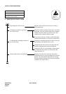
ATTENTION
Contents
Static Sensitive
Handling
Precautions Required
STEP 2
STEP 1
SLOT No.
PWR SW
0
LOAD
CPUOPE
PMOPE
WDT
1
2
3
4
5
6
PWR SW
Front Panel
Top Cover
CPR
SW PWR CA-A
SLOT No.
PWR SW
0
LOAD
CPUOPE
PMOPE
WDT
1
2
3
4
5
6
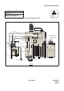
CPR
MISC CA-A
PWRSW
MB
front panel
lever
LED
screws
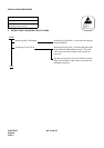
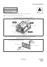
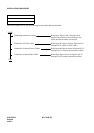
PassthetipofMBswitchthrough
thefrontpanellever.
LED
Front Panel
hole
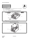
DonotbendtheLEDwhenattaching
thefrontpanel.PasstheLEDthrough
theholeonthefrontpanel.
Note 1:
Note 1
Note 2:
Note 2