


CHAPTER 3 ND-71548 (E)
Page 144
Issue 2
INSTALLATION PROCEDURE
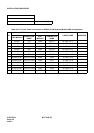
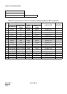
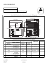
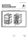
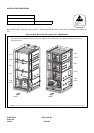
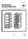
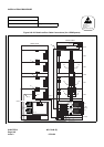
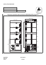
Run the bus cables, referring to Figure 010-27. Then, fasten the bus cables to the cabinet, referring to the figure be-
low.
Figure 010-26 Bus Cable Connections for 3-PIM System
NAP-200-010
Sheet 47/64
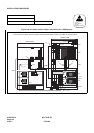
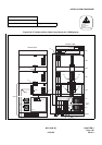
Internal Cable Connections Single IMG Configuration
ATTENTION
Contents
Static Sensitive
Handling
Precautions Required
MUSIC0
ALMB
ALMA
DSP
KEY
ALMA
ALM
BUS1A
BUS0A
TOP
MUSIC
MUX1
MUX2
MUX
LCON
LCON
LPM
(MGC)
PIM 0
PIM 1
FANU
PIM 2
LPM
(MGC)
PIM 0
PIM 1
PIM 2
FANU
ALMB
ALMA
MUX
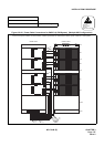
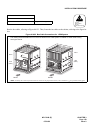
The drawing below illustrates how to run the bus cables for the 3-PIM system. For details on actual cable running,
see Figure 010-27.
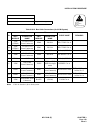
Note: Normally, the cable are fastened onto the cabinet at the proposed locations, where small dots ( ) are provided in this figure.
REAR FRONT
ALM
07/31/02