


CHAPTER 2 ND-71548 (E)
Page 32
Issue 2
INSTALLATION DESIGN
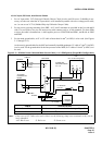
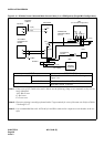
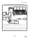
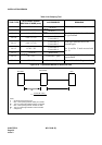
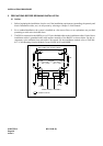
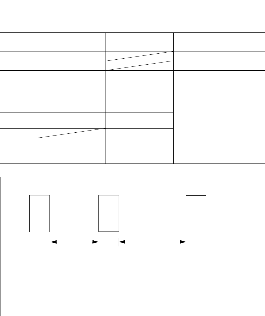
Figure 2-16 Calculation Method for Sectional Area
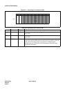
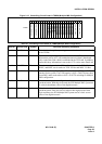
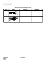
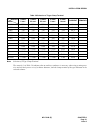
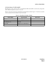
Table 2-10 Clamping Tool
*TOOL TYPE
APPLICABLE CROSS
SECTION OF WIRE (mm
2
)
ACCESSORIES REMARKS
No. 1 0.25 ~ 6.64 Manual type for A and C type terminal
No. 2 6.64 ~ 10.25
No. 9 6.64 ~ 42.42 Convex die 2 pieces Handling type hydraulic tool for A, C,
D, type terminal
No. 10 6.64 ~ 117.02
Convex die 4
Convex die 8
No. 11 6.64 ~ 117.02
Convex die 4
Convex die 8
Pedal type hydraulic tool for all
terminal types
No. 11 and No. 12 tools are used with
No. 13.
No. 12 117.02 ~ 325
Convex die 4
Convex die 4
No. 13 Rubber hose
No. 15 14 ~ 122 Convex die 7 pairs
Handling type hydraulic tool for T
type terminal
No. 16 123 ~ 365 Convex die 5 pairs Use with No. 13 for T type terminal
S =
RECTIFIER
BATTERY
PBX
0.018x(I
1M1+I2M2)
V
I
1M1
I2M2
where,
S : Sectional area required (mm2)
I1 : Max. current passing between battery and rectifier
M1 : Two-way cable length between battery and rectifier
I2 : Max. current passing between rectifier and PBX
M2 : Two-way cable length between rectifier and PBX
V : Voltage drop