


CHAPTER 5 ND-71548 (E)
Page 336
Issue 2
INSTALLATION TEST PROCEDURE
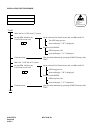
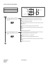
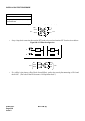
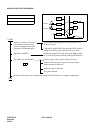
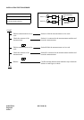
• If the TLT is a 4W E&M System, connect the related leads as shown below:
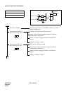
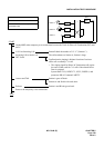
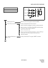
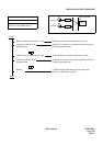
• Set up a loop-back connection between the DTI Trunk to be tested and another DTI Trunk as shown below:
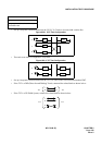
Figure 032-3 DTI Test Configuration
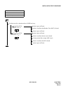
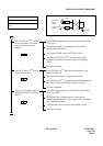
• If the office is the primary office (Clock-Source-Office), perform the tests by disconnecting the PLO and
the M-OSC. (The mode of the PLO becomes “Self Operation Mode.”)
NAP-200-032
Sheet 3/3
Outgoing Trunk (COT, TLT, DTI Card)
Connection Test
T
R
T
R
T
R
E
M
T
R
E
M
Re-
ceive
Send
Re-
ceive
Send
TLT TLT
E
M
E
M
LC DTIA
LCB
DTI
RA
RB
RA
RB
TA
TB
TA
TB
Re-
ceive
Send
Re-
ceive
Send
DTI DTI