


CHAPTER 3 ND-71548 (E)
Page 118
Issue 2
INSTALLATION PROCEDURE
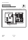
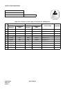
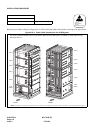
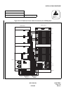
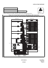
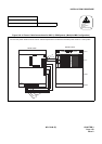
Run the power cables, referring to Figure 010-12. Then, fasten the cables to the cabinet, referring to the figure below.
Figure 010-11 Power Cable Connections for 4-PIM System
NAP-200-010
Sheet 21/64
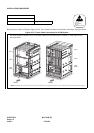
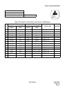
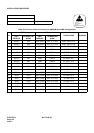
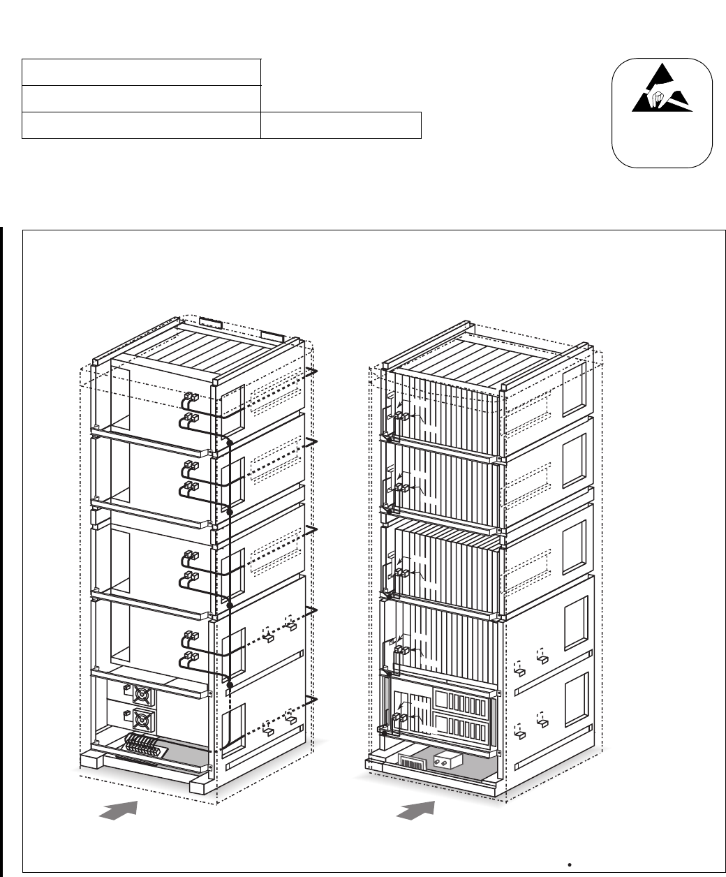
Internal Cable Connections Single IMG Configuration
ATTENTION
Contents
Static Sensitive
Handling
Precautions Required
LPM
(MGC)
PIM 0
PIM 1
FANU
PIM 2
PIM 3
LPM
(MGC)
PIM 0
PIM 1
PIM 2
PIM 3
FANU
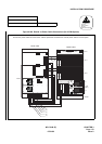
-48V0
-48V1
PWR A
PWR B
-48V0
-48V1
PWR A
PWR B
-48V0
-48V1
PWR A
PWR B
-48V0
-48V1
PWR A
PWR B
- 48 V0
- 48 V1
- 48 V0
- 48 V1
- 48 V0
- 48 V1
- 48 V0
- 48 V1
- 48 V0
- 48 V1
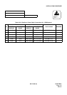
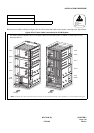
Note: Normally,thecablearefastenedontothecabinetattheproposedlocations,wheresmalldots()areprovidedinthisfigure.
REAR FRONT
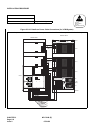
The drawing below illustrates how to run the power cables for the 4-PIM system. For details on actual cable running,
see Figure 010-12.
07/31/02