


ND-71548 (E) CHAPTER 3
Page 133
Issue 2
INSTALLATION PROCEDURE
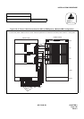
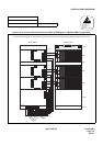
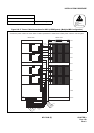
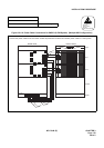
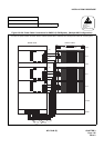
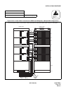
Figure 010-19 Power Cable Connections for IMG2/3 (2-PIM System) (Multiple IMG Configuration)
NAP-200-010
Sheet 36/64
Internal Cable Connections Multiple IMG Configuration
ATTENTION
Contents
Static Sensitive
Handling
Precautions Required
DUMMY
BASEU
PZ-M371
PA 1
PB 1
00 01 02 03 04 05 06 07 08 09 10 11 12 13 14 15 16 17 18 19 20 21 22 23
PWR
PWR
PH-PC36 (MUX0)
PH-PC36 (MUX1)
PIM 0
-48V IN
CONN
-48V IN
CONN
-48V0 PWR A
PWR B
-48V1
00 01 02 03 04 05 06 07 08 09 10 11 12 13 14 15 16 17 18 19 20 21 22 23
PWR
PWR
PH-PC36 (MUX0)
PH-PC36 (MUX1)
PIM 1
-48V IN
CONN
-48V IN
CONN
-48V0 PWR A
PWR B
-48V1
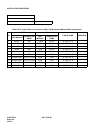
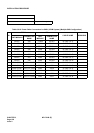
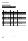
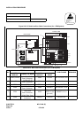
Connect the power cables as shown below. Cables represented in dotted-lines indicate power cable for a dual-system.
(1)
(2)
(3)
(4)
(6)
(5)
(8)
(7)
TOPU
PWR
ON
MJ MN MJ MN SUP/IP
SYSTEM ALM
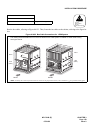
FRONT VIEWREAR VIEW
PA 2
PB 2