


CHAPTER 3 ND-71548 (E)
Page 166
Issue 2
INSTALLATION PROCEDURE
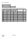
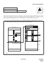
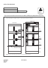
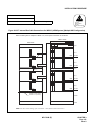
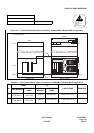
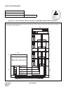
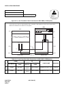
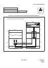
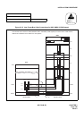
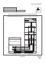
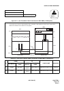
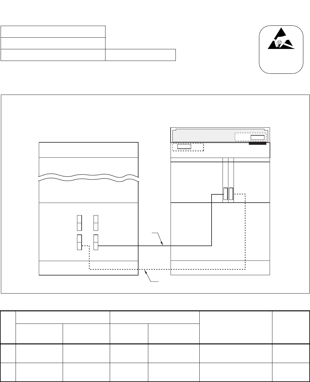
Figure 011-3 Inter-Frame Bus Cable Connections for IMG1-IMG2 (1-PIM System)
NAP-200-011
Sheet 5/24
Inter-Frame Cable Connections Multiple IMG Configuration
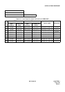
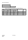
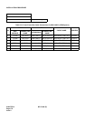
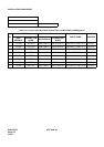
Table 011-3 Inter-Frame Bus Cable Connections for IMG1-IMG2 (1-PIM System)
No.
FROM TO
CABLE NAME REMARKS
UNIT/MODULE
CONNECTOR
NAME
UNIT/
MODULE
CONNECTOR
NAME
1TSWM MUX020
PIM0
(IMG2)
MUX (Slot13) 34PH MT24 TSW CA-F TSW 02
2TSWM MUX120
PIM0
(IMG2)
MUX (Slot14) 34PH MT24 TSW CA-F TSW 12
ATTENTION
Contents
Static Sensitive
Handling
Precautions Required
DUMMY
BASEU
TOPU
BASEU
TSWM
FRONT VIEWREAR VIEW
Connect the inter-frame bus cables between IMG1 and IMG2 (1-PIM system) as shown below. Note that the
dotted line indicates the bus cable for a dual-system.
IMG1
13 14
PH-PC36 (MUX0)
PH-PC36 (MUX1)
TOPU
PIM0
KEY
MUX
MUX
DSP
IMG2
(1)
(2)
(TSW12)
MUX120
(TSW02)
MUX020