


ND-71548 (E) CHAPTER 3
Page 237
Issue 2
INSTALLATION PROCEDURE
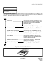
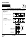
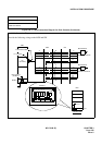
1. CABLE CONNECTION DIAGRAM
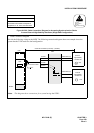
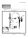
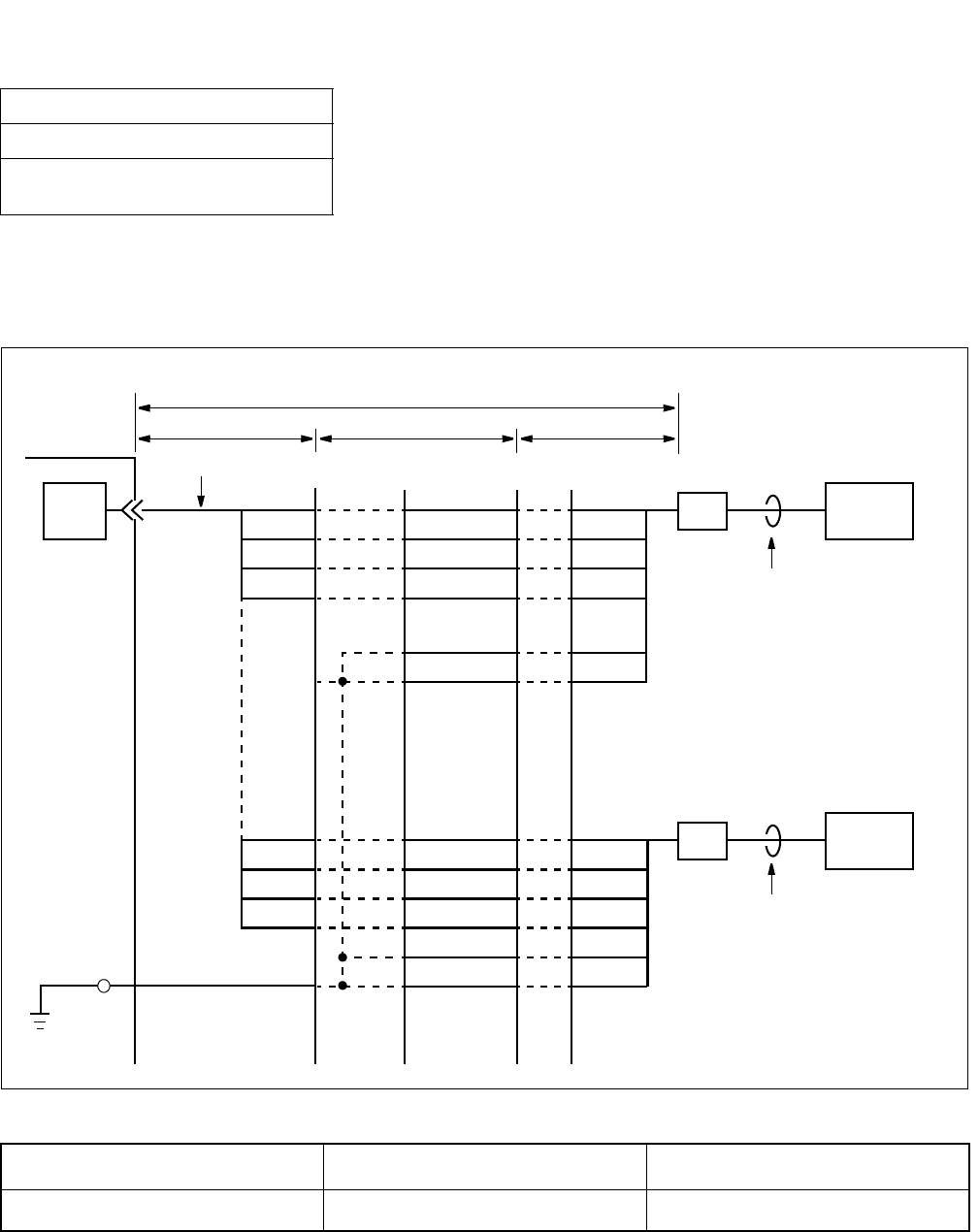
(a) When the power is supplied from the PBX
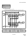
Figure 016-3 Cable Connection Diagram (When the Power Is Supplied from the PBX)
The maximum distance between the ATI circuit card and DESK CONSOLE is as shown below.
When exceeding the distance above, calculate the distance referring to the next page.
NAP-200-016
Sheet 5/44
Installation of the DESK CONSOLE and
Cable Connection
Source 0.5 φ Cable 0.65 φ Cable
PBX 350 m (1,148 ft.) 500 m (1,640 ft.)
GND
GND
A
B
BN4830
BN4831
A3
B3
GND
GND
A
B
A2
b c
M
a
PBX
ATI
MDF IDF
Installation Cable
B2
BN4820
BN4821
(–48V)
(–48V)
BN4820
BN4821
BN4830
BN4831
RPT1
DESK CONSOLE
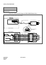
6-core Modular
Rosette
6-core Modular
Rosette
DESK CONSOLE
6-core Modular Cable
6-core Modular Cable