


ND-71548 (E) CHAPTER 3
Page 215
Issue 2
INSTALLATION PROCEDURE
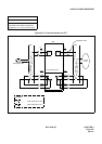
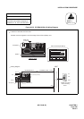
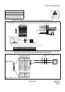
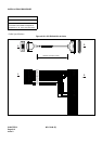
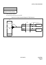
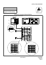
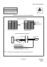
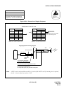
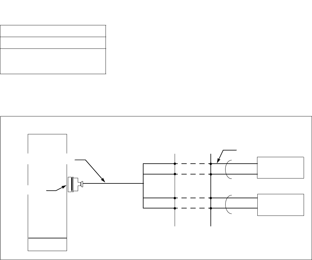
• Cable Connection Diagram
Provide the following connections at the MDF.
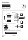
Figure 015-10 Cable Connection Diagram for TAS (Continued)
NAP-200-015
Sheet 15/32
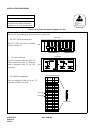
Cable Termination and Cross
Connections from MDF to Peripheral
Equipment, C. O. Lines, and Tie Lines
MDF
Installation Cable (1P)
TAS Indicator
TAS Indicator
TAS0A0
TAS0B0
TAS0A1
TAS0B1
PBX
LT connector Cable
LT connector