


ND-71548 (E) CHAPTER 3
Page 229
Issue 2
INSTALLATION PROCEDURE
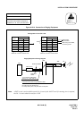
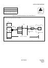
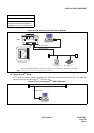
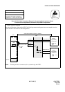
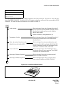
Figure 015-22 Cable Connection Diagram for Accepting Synchronization Clocks
from an External High-Stability Oscillator (Single IMG Configuration)
NAP-200-015
Sheet 29/32
Cable Termination and Cross
Connections from MDF to Peripheral
Equipment, C. O. Lines, and Tie Lines
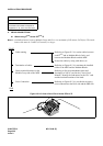
ATTENTION
Contents
Static Sensitive
Handling
Precautions Required
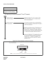
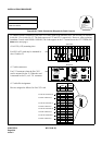
PLO
MDF
PBX
PCM Cable (IP)
PCM Cable (IP)
DCSA0
DCSB0
LT Connector Cable
DCSB1
DCSA1
TSW
BASEU
maximum 400 meters (1320 feet) (24AWG)
External
High-Stability
Oscillator #0
CLK
External
High-Stability
Oscillator #1
CLK
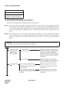
• Cable Connection Diagram
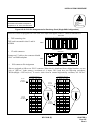
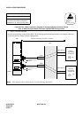
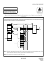
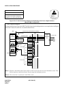
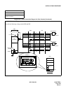
Provide the following wirings at the MDF. The following connection diagram shows an example where the
system has the TSW cards in a dual configuration.
Note: This diagram shows connections for a system having dual TSWs.
“PLO”