


ND-71548 (E) CHAPTER 3
Page 159
Issue 2
INSTALLATION PROCEDURE
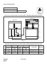
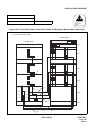
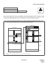
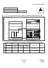
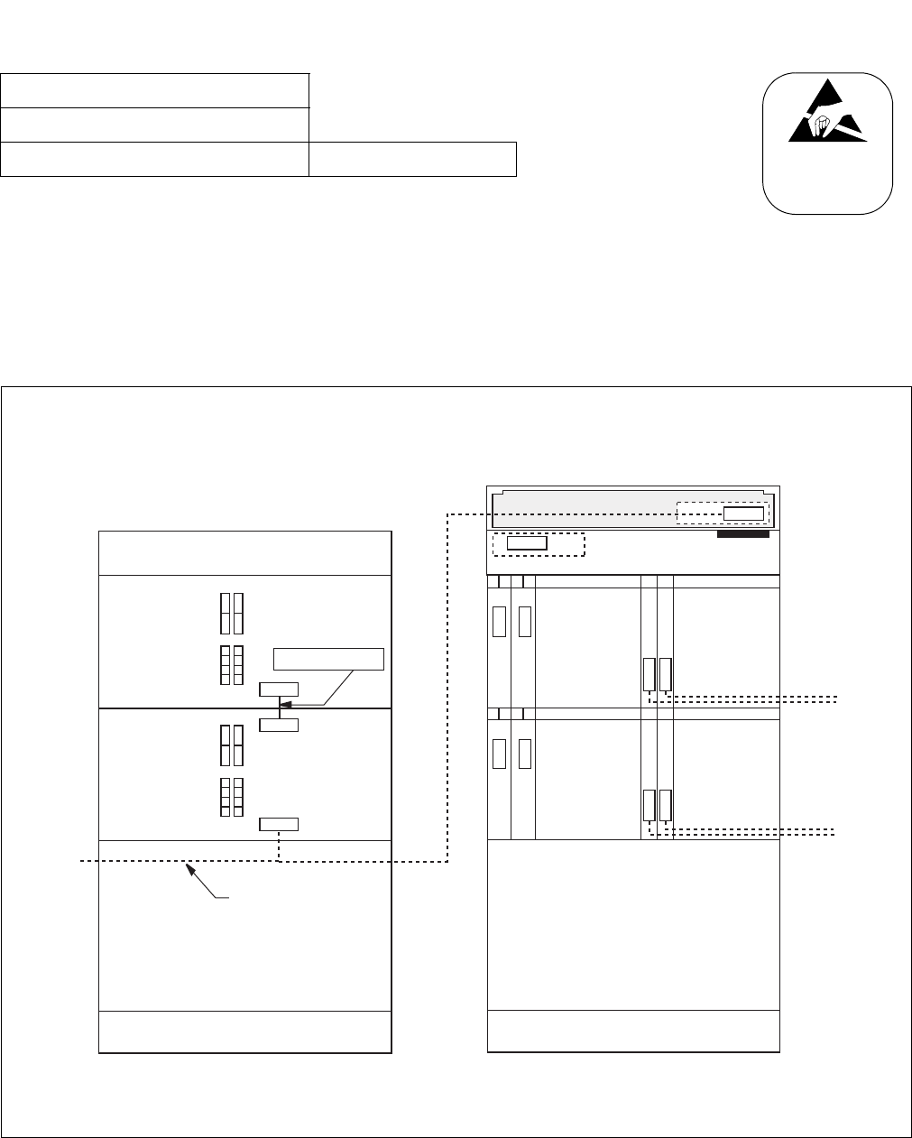
Figuers 010-35 through 010-37 show the configuration of the internal bus cables for IMG2/3. Because bus cables
for the 1-PIM system all adopt inter-frame connections with other cabinets (IMG0 and 1), explanations are given
here about the 2-PIM configuration or more. (cf. NAP 200-011; "Inter-frame Cable Connections.")
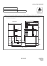
Figure 010-35 Internal Bus Cable Connections for IMG2/3 (2-PIM System) (Multiple IMG Configuration)
NAP-200-010
Sheet 62/64
Internal Cable Connections Multiple IMG Configuration
ATTENTION
Contents
Static Sensitive
Handling
Precautions Required
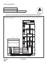
00 01 02 03 13 14
PH-PC36 (MUX0)
PH-PC36 (MUX1)
TOPU
PIM 0
DUMMY
BASEU
FRONT VIEW
REAR VIEW
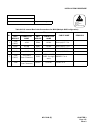
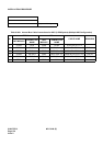
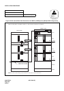
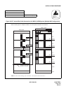
When 2-PIM system is adopted in IMG2 or 3, the required connection is as follows:
KEY
DSP
MUX
MUX
00 01 02 03 13 14
PH-PC36 (MUX0)
PH-PC36 (MUX1)
PIM 1
MUX
MUX
Note: For these cable running, refer to NAP-011: "Inter-frame Cable Connections."
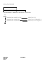
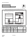
ALMA
ALMA
ALMB
To IMG1
To IMG1
To IMG0
Note
Note
Note
20AL-(10)FLT CA
DSPALM CA-B (for IMG2)
DSPALM CA-C (for IMG3)