


ND-71548 (E) CHAPTER 3
Page 193
Issue 2
INSTALLATION PROCEDURE
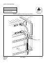
3. CONNECTIONS AT THE PBX SIDE
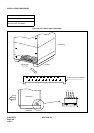
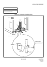
4. CABLE TYING AT THE PBX
NAP-200-013
Sheet 7/13
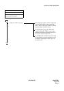
Cable Running from the PBX to MDF,
ATTCON, MAT, and SMDR
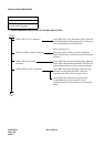
START
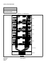
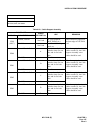
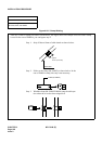
LT Connectors Confirm each connector name on the backplane
and the corresponding LT connector, then
connect the two.
EXALM Connector Connect the IPX EXALM CA-A to the EXALM
connector on the EMA card.
NCU Connectors Connect the NCU cable to the connector on the
front of the PFT card.
IOC Connectors Connect IPX 2PORT CA-A to the CONN0/1
connectors on the IOC card.
END
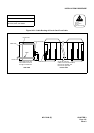
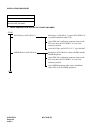
START
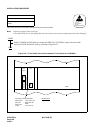
Referring to Figure 013-3, secure the connector cables to the Module.
END
ATTENTION
Contents
Static Sensitive
Handling
Precautions Required