


ND-71548 (E) CHAPTER 3
Page 205
Issue 2
INSTALLATION PROCEDURE
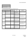
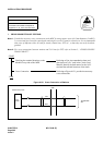
3. CROSS CONNECTIONS FOR PFT
Note 1:
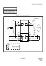
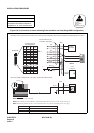
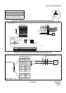
The COT must be accommodated in a universal slot of the same Unit (U) in which the cross-connected PFT
is mounted. See the figure below.
Note 2: Provide the necessary cross connections at the MDF by using copper wires of 0.5 mm diameter (24 AWG).
2-core twisted wire is used for speech path, and single-core wire is used for control wire. It is recommended
that wires of different colors be used for trunks, station lines, PFT, etc., so that they can easily be distin-
guished.
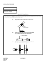
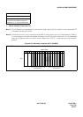
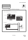
Figure 015-3 Mounting Locations of PFT (PA-M53)
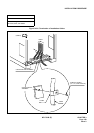
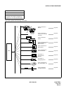
NAP-200-015
Sheet 5/32
Cable Termination and Cross
Connections from MDF to Peripheral
Equipment, C. O. Lines, and Tie Lines
00 01 02 03 04 05 06 07 0809 10 11 12 13 14 15 16 17 18 19 20 21 22 23
PFT (PA-M53)
MUX/TSW
PIM
The PFT (PA-M53) card is mounted in slot 04 or in slot 15 of each PIM.
FRONT VIEW
COT
MUX/TSW
PFT (PA-M53)
Universal Slots
Universal Slots