


ND-71548 (E) CHAPTER 3
Page 139
Issue 2
INSTALLATION PROCEDURE
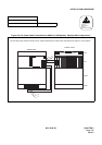
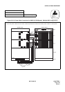
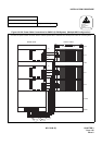
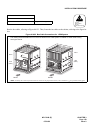
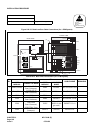
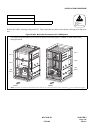
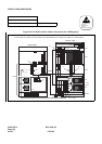
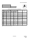
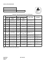
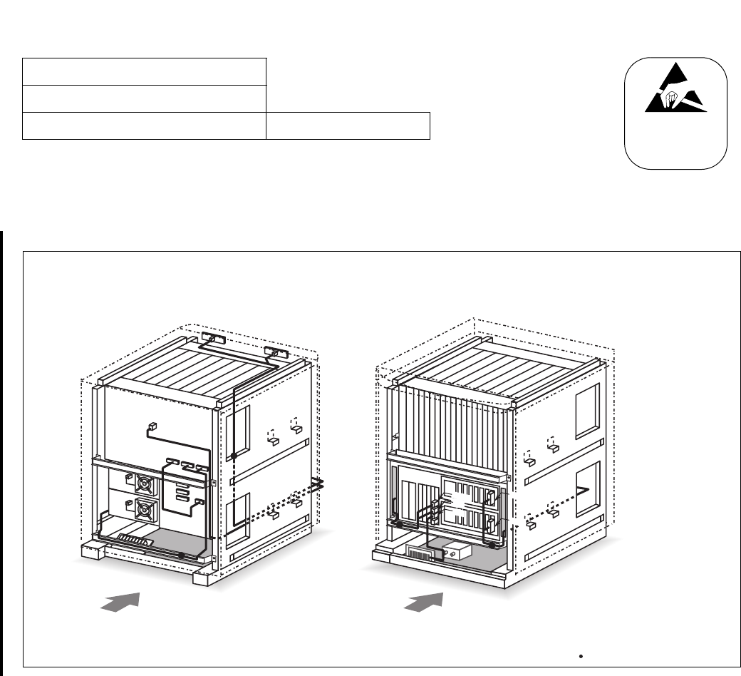
Run the bus cables, referring to Figure 010-23. Then, fasten the bus cables to the cabinet, referring to the figure be-
low.
Figure 010-22 Bus Cable Connections for 1-PIM System
NAP-200-010
Sheet 42/64
Internal Cable Connections Single IMG Configuration
ATTENTION
Contents
Static Sensitive
Handling
Precautions Required
MUSIC0
DSP
KEY
ALMA
ALM
BUS1A
BUS0A
TOP
MUSIC
LCON
LCON
TOP
ALM
LPM
(MGC)
PIM 0
LPM
(MGC)
PIM 0
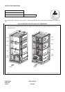
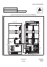
Note: Normally, the cable are fastened onto the cabinet at the proposed locations, where small dots ( ) are provided in this figure.
REAR FRONT
The drawing below illustrates how to run the bus cables for the 1-PIM system. For details on actual cable running,
see Figure 010-23.
07/31/02