


CHAPTER 3 ND-71548 (E)
Page 214
Issue 2
INSTALLATION PROCEDURE
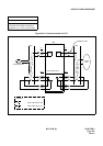
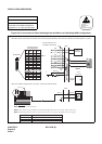
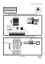
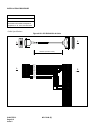
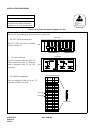
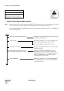
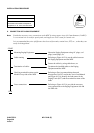
Figure 015-10 Cable Connection Diagram for TAS
NAP-200-015
Sheet 14/32
Cable Termination and Cross
Connections from MDF to Peripheral
Equipment, C. O. Lines, and Tie Lines
ATTENTION
Contents
Static Sensitive
Handling
Precautions Required
PIN
No.
26
27
LEAD
NAME
PIN
No.
1
2
LEAD
NAME
32
33
34
35
36
37
38
39
40
41
42
43
44
45
46
47
48
49
50
7
8
9
10
11
12
13
14
15
16
17
18
19
20
21
22
23
24
25
BN4800
BN4820
TAS1B
BN4810
TAS0B
BN4830
B2
B3
BN4801
BN4821
TAS1A
BN4811
TAS0A
BN4831
A2
A3
LT Connector
for TAS #1
for TAS #0
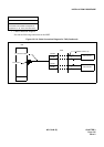
00 01 02 03 04 05 06 07 08 09 10 11 12 13 14 15 16 17 18 19 20 21 22 23
Front View
Backplane
PIM
PIM
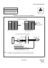
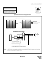
PA-CS33 Pin Assignment
Universal Slots
Universal Slots
PA-CS33(ATI)
PA-CS33(ATI)
TSW/MUX
TSW/MUX
LT11
LT5
LT5
LT11
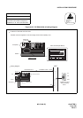
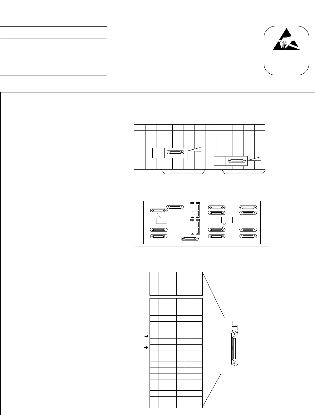
To connect TAS the PA-CS33 card is used as the interface card. The card may be mounted in Slot No. 12 or in
Slot No. 23. The leads appear on LT5 and LT11, respectively.
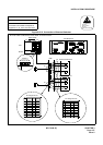
• PA-CS33 (ATI) mounting slots
PA-CS33 (ATI) card may be mounted
in Slot 12
and/or 23.
• LT cable connectors
Use LT5 connector when the PA-CS33
card is mounted in Slot 12. When the
card is mounted in Slot 23, use LT11
connector.
• LT cable Pin Assignment
Pins are assigned as follows on the LT
connector for PA-CS33 card.