


ND-71548 (E) CHAPTER 3
Page 249
Issue 2
INSTALLATION PROCEDURE
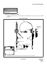
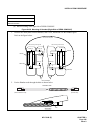
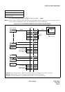
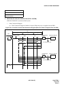
(a) When using three DESK CONSOLEs and one recorder Note 1
Note 1:
Switch settings of SW10, SW12 and SW13 on the PA-M87 card are required. For switch setting and con-
nector lead accommodation, refer to the NEAX2400 IPX Circuit Card Manual.
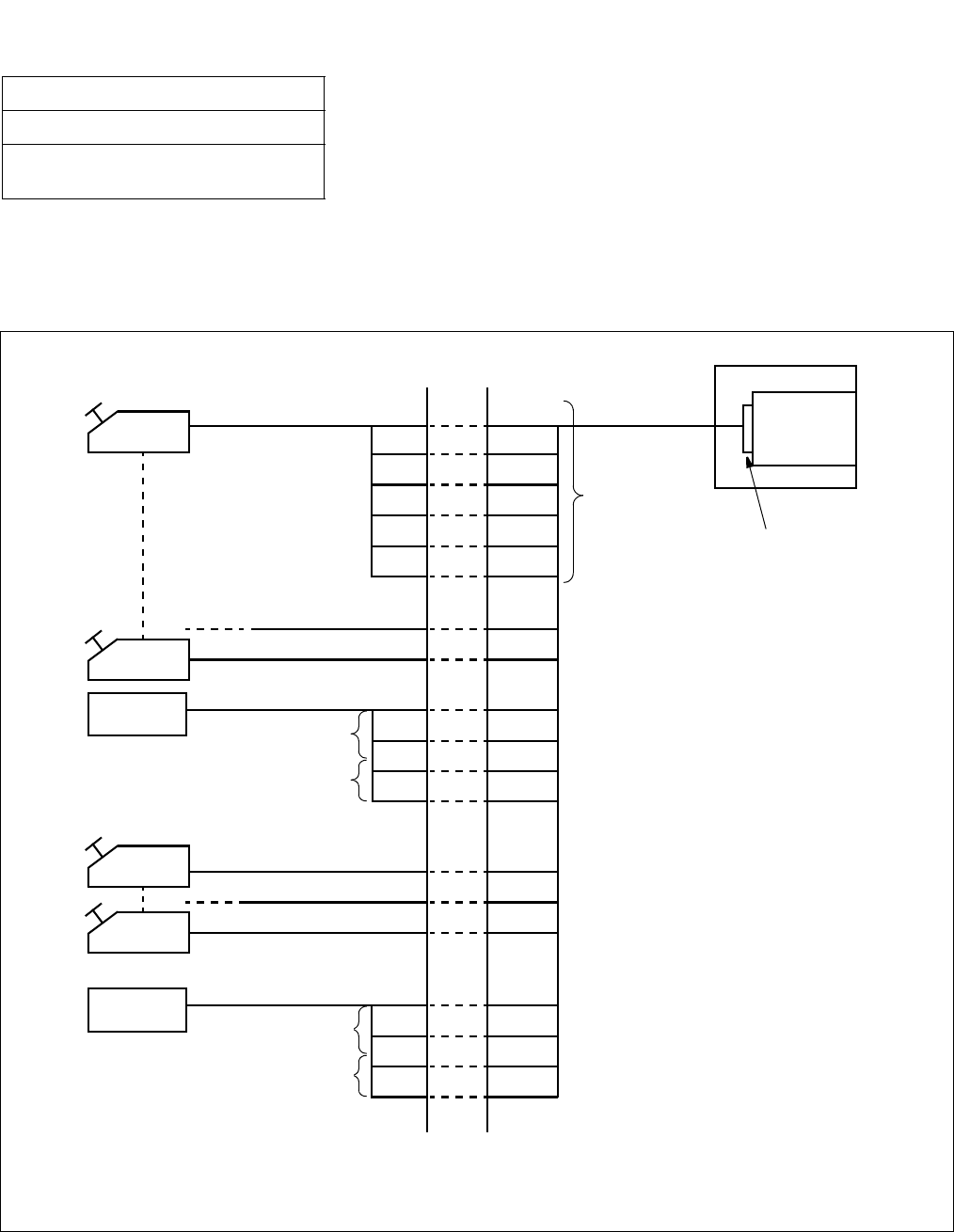
Figure 016-10 Three DESK CONSOLEs and One Recording Equipment
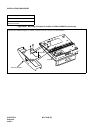
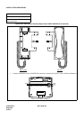
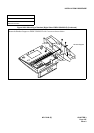
NAP-200-016
Sheet 17/44
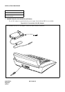
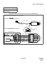
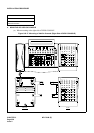
Installation of the DESK CONSOLE and
Cable Connection
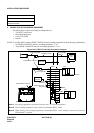
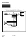
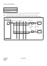
Note 2: Refer to Figure 016-9 ”RECC Card Cable Connection Diagram” for cable connection.
Note 3: Connections of Circuit 1 through 5 are the same as those of Circuit 0.
Note 4: Recording equipment is positioned between the C.O. line and telephones.
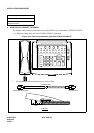
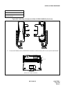
DESK CONSOLE
Note 2
MDF
Note 2
PIM
RECC
card
Circuit 0
Note 3
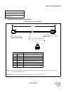
Front Connector
A
B
LA
LB
KA
KB
A0
B0
M0A
M0B
K0A
K0B
Circuit 1
Circuit 2
L0A
L0B
T0A
T0B
Circuit 3
Circuit 4
Circuit 5
L1A
L1B
T1A
T1B
C.O. line side
leads
Telephone side
leads
Recording
Equipment
Recording
Equipment
Note 4
Note 4
C.O. line side
leads
Telephone side
leads
Note 4
Note 4