


ND-71548 (E) CHAPTER 3
Page 153
Issue 2
INSTALLATION PROCEDURE
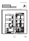
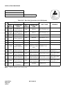
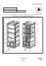
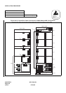
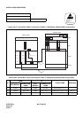
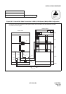
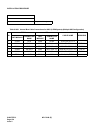
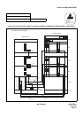
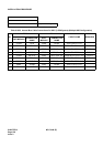
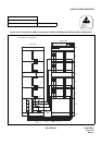
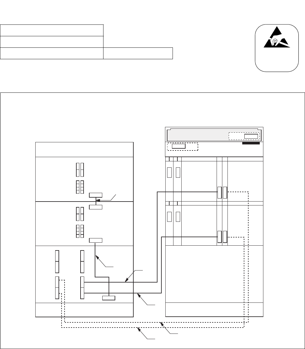
Figure 010-32 Internal Bus Cable Connections for IMG1 (2-PIM System) (Multiple IMG Configuration)
NAP-200-010
Sheet 56/64
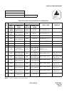
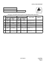
Internal Cable Connections Multiple IMG Configuration
ATTENTION
Contents
Static Sensitive
Handling
Precautions Required
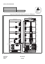
00 01 02 03 13 14
PH-PC36 (MUX0)
PH-PC36 (MUX1)
TOPU
PIM 0
TSWM
BASEU
FRONT VIEW
REAR VIEW
Connect the internal bus cables for 2-PIM system of IMG1 as shown below. Note that dotted-line indicates
bus cables for a dual-system.
(2)
(4)
(3)
(5)
KEY
MUX110 MUX010
MUX111 MUX011
MUX112 MUX012
MUX113 MUX013
(1)
DSP
MUX
MUX
00 01 02 03 13 14
PH-PC36 (MUX0)
PH-PC36 (MUX1)
PIM 1
MUX
MUX
(6)
ALM
ALMA
ALMA
ALMB
(TSW11) (TSW01)