


ND-71548 (E) CHAPTER 3
Page 255
Issue 2
INSTALLATION PROCEDURE
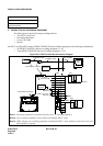
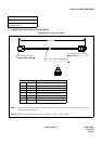
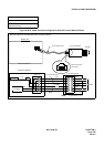
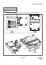
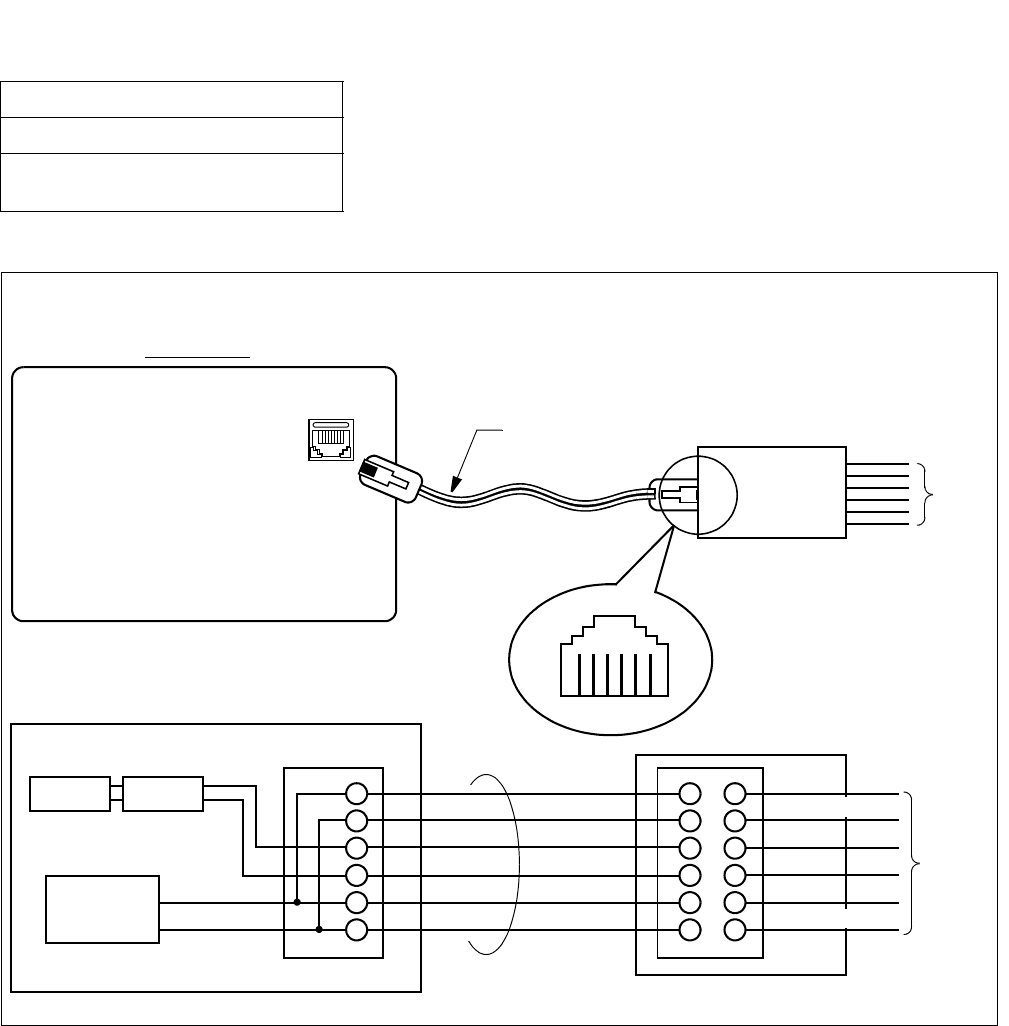
Figure 016-16 Cable Connection Diagram for Add-On Console Modular Block
NAP-200-016
Sheet 23/44
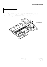
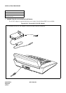
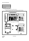
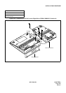
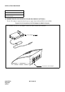
Installation of the DESK CONSOLE and
Cable Connection
Wire the cables to the Modular Block as shown below.
Modular Jack
Bottom View
ADD-ON CONSOLE
LINE
(6-core)
6-core Modular Cable
6-core Modular Block
IDF/MDF
Viewed from direction
to be inserted
1 2 3 4 5 6
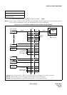
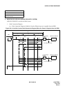
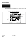
ADD-ON CONSOLE
Transformer
Surge
Protection
DC/DC
Convertor
GND
–48V/–24V
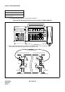
Add-On Console
Modular Jack
6-core Modular Cable
6-core Modular Block
GND
Ax Note
Bx Note
GND
IDF/MDF
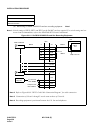
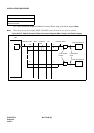
Note: x represents 0 or 1.
BN48×0(–48V)
BN48×1(–48V)
GND
BN48×0(–48V)
Ax Note
Bx Note
GND
BN48×1(–48V)