


CHAPTER 2 ND-71548 (E)
Page 26
Issue 2
INSTALLATION DESIGN
9.3 Preparation of Trunking Diagram
Prepare the trunking diagram for the customer’s specification. Since there are different types of switching of-
fices (such as a single office, network offices, etc.) are involved, the trunking diagram must be prepared for each
of the customer’s specification.
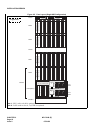
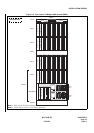
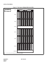
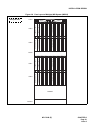
9.4 Preparation of Module Group Face Layout And Port Accommodation Diagram
To mount circuit cards in the PBX, the company, which is supposed to install the IPX, should prepare the face
layout of module group and port accommodation diagram.
9.5 Preparation of Circuit Card Switch Setting Sheets
Prepare the switch setting sheets for the circuit cards to be mounted in the PBX. Some of the circuit cards might
not be operated properly with the initial settings due to some reason such as not meet the customer’s specifica-
tion. Refer to the Circuit Card Manual describing the switch settings on Switch Setting Sheets and make sure
the switch setting entries.
Keep in mind that the card needs settings suitable for the surroundings.
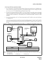
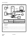
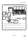
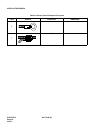
10. INSTALLATION CABLES
The following installation cables are required for the PBX:
• DC Power Cable: For connections between the Rectifier and battery and be-
tween the Rectifier and the PBX
• AC Power Cable: For supplying AC source power to the Rectifier
• Ground Cable: Communication, Security and Line Protector grounding
• 25P Shielded Cable with CHAMP
• (Amphenol) connector at one end: For connections between the MDF and the PBX
• 25P Shielded Cable with CHAMP
• (Amphenol) connector at both ends: For connections between the MAT and the PBX, and be-
tween peripheral equipment and the PBX
• House Cable: For connections between terminals (telephone sets, etc.) and
the MDF
• Cables for C.O. lines and Tie Lines
• Others: For connections between Alarm Indicators and the MDF