


CHAPTER 3 ND-71548 (E)
Page 232
Issue 2
INSTALLATION PROCEDURE
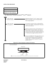
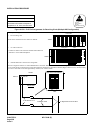
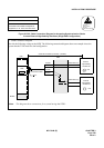
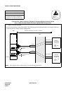
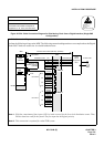
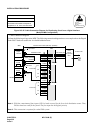
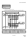
Figure 015-25 Cable Connection Diagram for Distributing Clock from a Digital Interface
(Multiple IMG Configuration)
NAP-200-015
Sheet 32/32
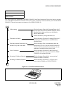
Cable Termination and Cross
Connections from MDF to Peripheral
Equipment, C. O. Lines, and Tie Lines
ATTENTION
Contents
Static Sensitive
Handling
Precautions Required
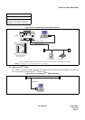
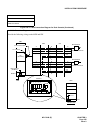
EXCLK1
EXCLK0
maximum 100
meters (330 feet)
MDF
IMG1
PCM
Carrier
Equipment/
DSU
CLK
PCM Cable (2P)
LT Connector
“EXCLK0”
“EXCLK1”
PLO#0
PLO#1
BASEU
to other node
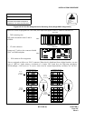
RA
RB
TA
TB
POUTA
POUTB
DIU0A
DIU0B
DIU1A
DIU1B
DIU2A
DIU2B
DIU3A
DIU3B
DIU0A
DIU0B
DIU1A
DIU1B
DIU2A
DIU2B
DIU3A
DIU3B
#1
#2
#3
#4
#1
#2
#3
#4
for PLO #0
for PLO #1
Installation Cable
Installation Cable
Installation Cable
Digital
Interface
(24AWG)
Note 1
Note 2
Note 1: PLO has a maximum of four inputs. DIU1xx leads are used for the first clock distribution routes. Thus,
DIU4xx leads are used for the fourth. The first input has the highest priority.
Note 2: This connection is required for a dual-PLO system.
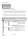
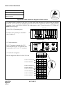
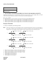
• Cable Connection Diagram
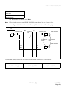
Perform the following wirings at the MDF. The following connection diagram shows an example where the Digital
Trunk POUT leads are used as the 1st clock distribution route.
maximum 200 meters (660 feet) (24AWG)