


11
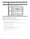
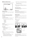
● Sequence Mode
More than one camera's images are sequentially displayed for a
fixed time.
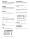
The illustration shows an example of the sequential display of
images through Camera 2, 4, and 6 on Monitor 1.
Before use, the parameters* of the sequence need to be config-
ured and uploaded to the unit.
* Example: Camera selection, monitor selection, and dwell time
(the time to display each image).
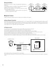
■ System Control
System controllers are used to control the equipment connected to this system.
●
About System Controller
This matrix switcher system has four data ports: DATA 1 to 4. The ports DATA 1 to 3 supports the terminal mode, and the
DATA 4 port supports both the terminal mode and Panasonic Security Data (PS·Data) Systems. These are the operation mode
of the matrix switcher. When using the DATA 4 port, you can employ either of them. Refer to p. 14 for details of the terminal
mode. Refer to p. 22 for notification about PS·Data System.
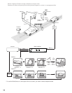
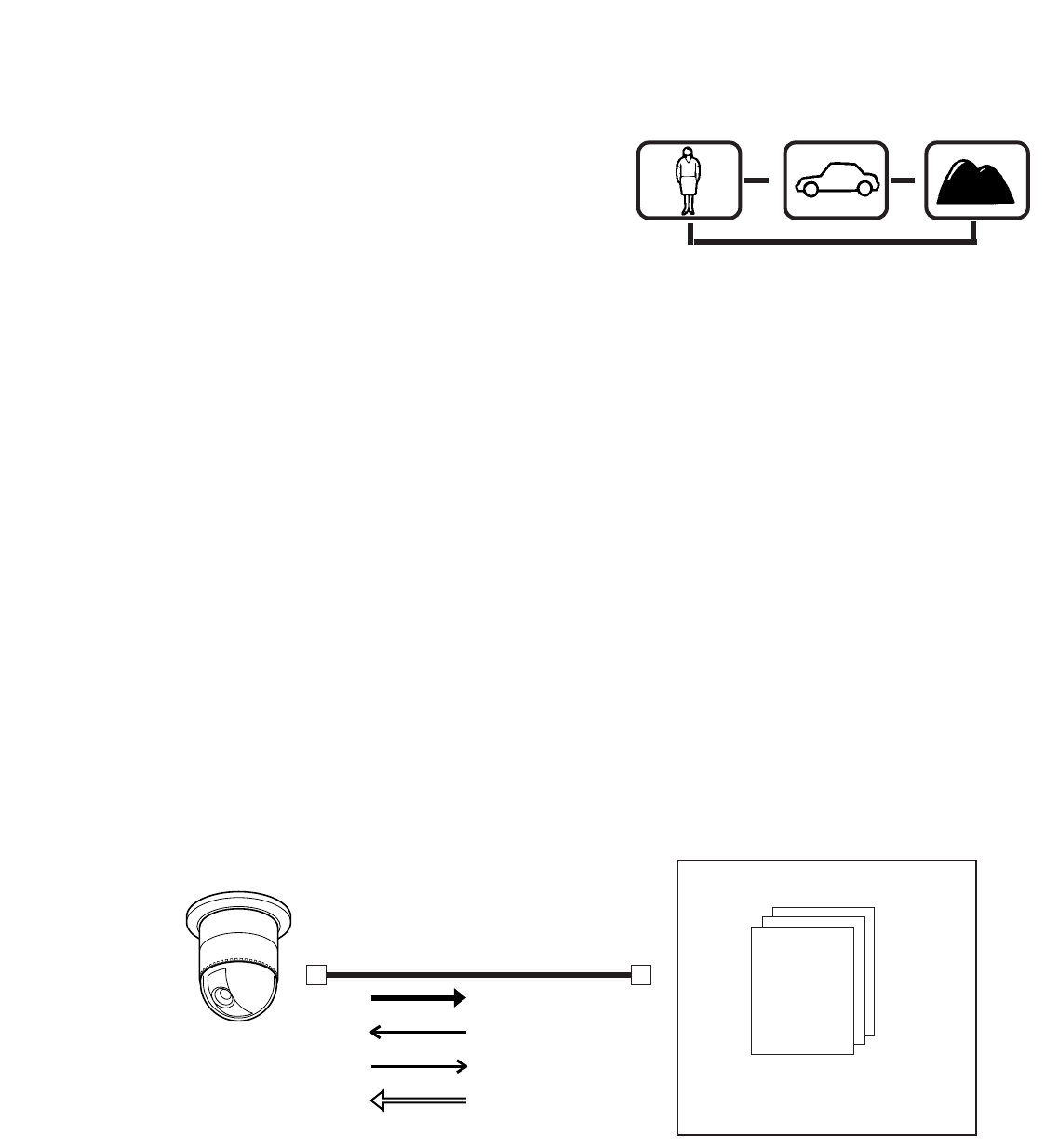
●
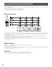
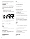
Camera control
As the illustration, this unit sends the control data and VD2 timing pulse to the cameras.
On the contrary, the cameras send the video signal and state signal to the unit.
Control data is supplied via the coaxial cable from the unit, multiplexed with the camera image.
The unit is equipped with the circuit to multiplex or separate the video signal and control data with each channel.
These connections enable the control of the equipment from the system controller.
When using Panasonic RS-485 cameras, the unit can send the separated control data to them.
RS-485 cameras can be installed at longer distance from the matrix switcher than cameras that multiplex the control data.
Each signal functions as the illustrations in the next page.
VD2 provides the timing pulse of the same phase to prevent the unconformity during the switching of the image in a sequence
mode.
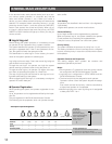
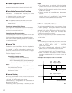
Multiplexed
data
Sync
signal
Every channel is equipped with
multiplexed data and sync
signal.
Matrix switcher
Coaxial cable
Video signal
Control signal
Status signal
Timing pulse (VD2)
Combination camera
Monitor 1
Dwell time: 2 sec.
Step 1
Monitor 1
Dwell time: 2 sec.
Step 2
Monitor 1
Dwell time: 2 sec.
Step 3
s
s
s
Camera 2
Camera 4 Camera 6