


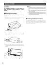
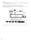
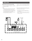
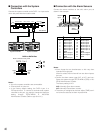
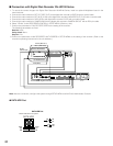
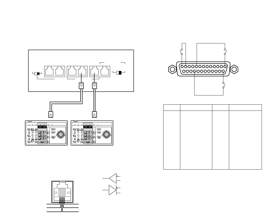
■ Connection with the Alarm Sensors
Connect the sensor switches to the unit's alarm port, as
shown in the example.
Notes:
• Alarm inputs that are simultaneous or with very short
intervals will be ignored.
Allow for at least 100 ms interval from one alarm input to
the next.
• Confirm the alarm sensor type (N.O. or N.C.) and con-
figure the system through SETUP MENU (OSD) or WJ-
SX150 Administrator Console.
The factory setting is N.O.
N.O.: Normally Open alarm contact
N.C.: Normally Closed alarm contact
• The alarm pin assigned to the time adjust (TIME) termi-
nal cannot be used as an alarm input terminal.
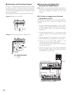
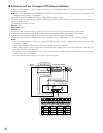
25
13
14
1
Alarm
Sensor 1
Alarm
Sensor 2
ALARM
Recover
Input
1
2
3
4
5
6
7
8
9
10
11
12
13
Alarm Input 1
Alarm Input 3
Alarm Input 5
Alarm Input 7
Alarm Input 9
Alarm Input 11
Alarm Input 13
Alarm Input 15
GND
Alarm Output 1
Alarm Output 3
GND
Recover Input
Pin No. Designation
14
15
16
17
18
19
20
21
22
23
24
25
Alarm Input 2
Alarm Input 4
Alarm Input 6
Alarm Input 8
Alarm Input 10
Alarm Input 12
Alarm Input 14
Alarm Input 16
GND
Alarm Output 2
Alarm Output 4
GND
Pin No. Designation
40
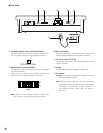
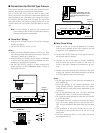
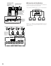
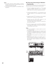
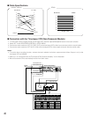
■ Connection with the System
Controllers
Connect the system controller to the DATA 1 to 4 port at the
unit's rear panel with the modular cable.
Notes:
• Up to four system controllers are connectable.
• Connect them in home run.
• In the factory default setting, the DATA 4 port is a
PS·Data terminal. To connect a terminal-mode system
controller to this port, you need to change the data port
setting through SETUP MENU or WJ-SX150
Administrator Console. (Refer to pp. 60 or 81.)
WJ-SX150
System controllerSystem controller
2
DATA 3 DATA 2
TERM
OFF ON
4
RS485(CAMERA)
LINE
SELECT
RS485(CAMERA)PS•DATA
DATA 4DATA HDR DATA 1
NEXT
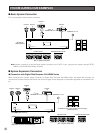
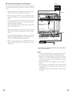
For Matrix Switcher (WJ-SX150)
WV
-
CU C
360
System Controller
NEXT
For Matrix Switcher (WJ-SX150)
WV
-
CU C
360
System Controller
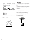
RB
RA
TB
TA
GND
GND
Matrix switcher's rear panel
DATA 1 to 4
TB
TA
RB
RA
DATA1 to DATA4 Port