


38
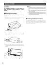
■ Connections for RS-485 Type Camera
There are two options to connect the camera with the matrix
switcher, depending on the distance between them.
One is "Home Run" wiring and the other is daisy chain
wiring. "Home Run" wiring has the transmission stability with
less transmission loss, and daisy chain wiring has connec-
tion flexibility with less data ports occupied. For data-multi-
plex type cameras, 900 meters (3 000 ft) is the limit to use
coaxial cable such as RG-59/U, BELDEN 9259 or equiva-
lent.
Note: If more distance is required, use cameras and
matrix switcher with RS-485 communication feature.
Remote control becomes possible.
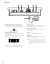
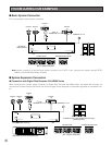
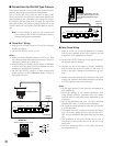
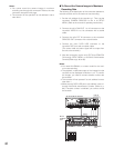
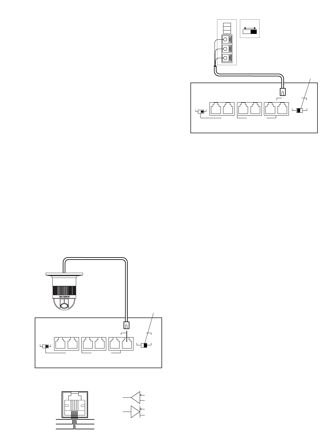
● "Home Run" Wiring
1. Connect with a RS-485 camera in "Home Run" wiring as
shown in the figure.
2. Set the LINE SELECT switch to 2 or 4.
Notes:
• Before connecting RS-485 cameras to DATA1 to 3, data
port setting through WJ-SX150 Administrator Console is
necessary. (Refer to p. 81 Data Port.)
• Recommended for RS-485 communication is AWG#22
or thicker one. The cable should be shielded, two-wire,
twisted pair, and with low impedance.
• Set the LINE SELECT switch to 4 when programming
preset position of WV-CSR600/650 Series camera is
connected to the unit.
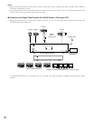
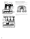
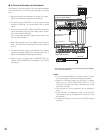
● Daisy Chain Wiring
1. Draw up a plan for connection between the cameras
and the input channels of the matrix switcher, and the
assignment of unit addresses to cameras.
2. Set the LINE SELECT switch to 2. Also, set the connect-
ed device's switch if required.
3. Connect one end of the cable to RS-485 (CAMERA),
and the other end to the first camera in the chain, as
shown in the figure. Repeat this procedure for all cam-
eras.
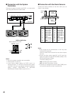
4. Set the termination switches of the cameras at the chain
ends to ON. Camera's termination switches must be set
to OFF except the ones at the chain ends.
Notes:
• Set the same number for the camera's unit address as
and CAMERA IN.
• Check the settings of the camera addresses when
using RS-485 cameras. Operations from the system
controller will be invalid if the camera addresses are set
improperly.
• Do not use addresses other than 1 to 16 for individual
cameras (More than 17 cameras are not allowed).
• Do not set the same address for more than one camera
in an RS-485 chain.
• Termination is the key to data transmission and recep-
tion in the chain. While the other switches are set to
OFF, only the switches at the chain ends must be set to
ON.
• The termination of this unit's RS-485 camera port is
always set to ON. Connect the unit at the end of the
daisy chain.
• The more equipment there is in the chain, the slower
the response may be.
WJ-SX150
RS-485 type camera
2
DATA 3 DATA 2
TERM
OFF ON
4
RS485(CAMERA)
LINE
SELECT
RS485(CAMERA)
DATA 4
PS•DATA
DATA HDR DATA 1
Set it to
position 4.
WV-CPR450 and others (For the
Termination Switch positions, refer
to the oprating instractions of the
camera.)
(A)
(B)
GND
OFF ON
WJ-SX150
2
DATA 3 DATA 2
TERM
OFF ON
4
RS485(CAMERA)
LINE
SELECT
RS485(CAMERA)
DATA 4 DATA 1
Set it to
position 2.
DATA HDR
PS•DATA
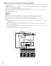
RB
RA
TB
TA
GND
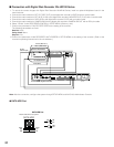
None
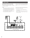
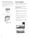
Matrix switcher's rear panel
TB
TA
RB
RA
RS485 Port