


57
OFF: An alarm input is not accepted via the ALARM
port.
The factory default setting is ON.
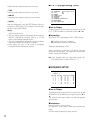
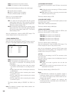
Each alarm input's polarity is configurable in 440 ALARM
INPUT (ALARM PORT).
Set ALARM PORT to ON or REC ONLY, and press the CAM
(SET) button.
440 ALARM INPUT (ALARM PORT) will appear on the moni-
tor.
To select an alarm input polarity required for the ALARM
port, press the PREV or NEXT button.
N.O.: Selects Normally Open alarm contact.
N.C.: Selects Normally Closed alarm contact.
TIME: Enables the input for time adjustment.
The factory default setting is N.O.
Notes:
• Use N.O. type master clock.
• If TIME is selected, an alarm input terminal can adjust
the clock by ±30 seconds with an N.O. type signal
input. For example, when the clock time is between
00:59:30 and 01:00:30, it will be automatically adjusted
to 01:00:00 by the master clock.
After the configuration, press the MON (ESC) button. The
monitor display returns to 400 ALARM SETUP.
SERIAL PORT
This stands for that an alarm input is accepted via the
SERIAL port. The alarm-associated sequence/ spot
image is displayed on a monitor, and alarm recording
will start (if a recorder is connected to the unit).
ON: The alarm-associated sequence/spot image is dis-
played on a monitor, and alarm recording will start
(if a recorder is connected to the unit.)
REC ONLY: Only alarm recording will start and moni-
tors will keep displaying the current sequence/spot
images.
Note: You cannot recover alarm-related operations
from system controllers when REC ONLY is
selected.
OFF: An alarm input is not accepted via the SERIAL
port.
The factory default setting is ON.
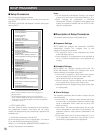
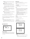
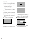
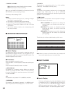
• PRE: This item stands for the preset position num-
ber of a CAMnn. Enter the desired preset position
number when selecting a combination camera.
When selecting another type of camera, select --.
• TOURnn (nn is a tour sequence number): Executes
a tour sequence when an alarm input is accepted.
The factory default setting is the same as the two illustra-
tions above.
Notes:
• MODE and PRE cannot be selected by pressing the
numeric buttons. Press the NEXT or PREV button for
selection.
• PRE doesn’t appear when TOUR 1 to 16 is selected for
MODE.
• When selecting a camera without the preset position
function, select "- -" for PRE.
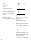
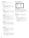
• When moving the joystick to ▼ at the bottom of ALARM
EVENT 1 of 2, the monitor will display 2 of 2 (the next
page).
• When moving the joystick to ▲ at the top of ALARM
EVENT 2 of 2, the monitor will display 1 of 2 (the previ-
ous page).
After the configuration, press the MON (ESC) button. The
monitor display returns to ALARM SETUP.
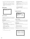
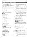
• ALARM INPUT
CAMERA
This stands for that an alarm input is accepted via the
CAMERA IN connectors or the RS-485 ports.
ON: The alarm-associated sequence/spot image is dis-
played on a monitor, and alarm recording will start
(if a recorder is connected to the unit).
REC ONLY: Only alarm recording will start and moni-
tors will keep displaying the current sequence/spot
images.
Note: You cannot recover alarm-related operations
from system controllers when REC ONLY is
selected.
OFF: An alarm input is accepted neither via the CAM-
ERA IN connectors nor the RS-485 ports.
The factory default setting is OFF.
ALARM PORT
This stands for that an alarm input is accepted via the
ALARM port (25-pin D-sub connector at the rear panel).
ON: The alarm-associated sequence/spot image is dis-
played on a monitor, and alarm recording will start
(if a recorder is connected to the unit.)
REC ONLY: Only alarm recording will start and moni-
tors will keep displaying the current sequence/spot
images.
Note: You cannot recover alarm-related operations
from system controllers when REC ONLY is
selected.
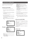
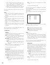
440 ALARM INPUT(ALARM PORT)
1 N.O. 9 N.O.
2 N.O. 10 N.O.
3 N.O. 11 N.O.
4 N.O. 12 N.O.
5 N.O. 13 N.O.
6 N.O. 14 N.O.
7 N.O. 15 N.O.
8 N.O. 16 N.O.