


25
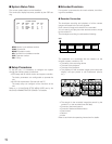
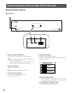
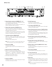
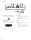
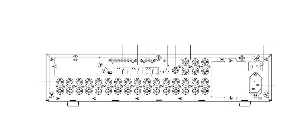
● Rear View
SIGNAL GND
POWER
AC IN
CAMERA
1
1
2
2
3
3
2
DATA 3 DATA 2
SERIALALARM
TERM
OFF ON
4
2
1
4
3
CAMERA
SW IN
RS485(CAMERA)
LINE
SELECT
MONITOR OUT
EXT IN
(PLAY IN)
EXT OUT
(REC OUT)
OUT
IN
4
4
5
5
6
6
7
7
8
8
9
9
10
10
11
11
12
12
13
13
14
14
15
15
16
16
RS485(CAMERA)
DATA 4DATA HDR
PS•DATA
DATA 1
t
y
uio!0
!1 !2 !3!4 !5 !6
!9
!7 !8
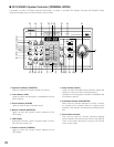
t Camera Output connectors (CAMERA OUT 1–16)
The video signal connected to the CAMERA IN connec-
tor is supplied at these connectors.
When the power of the matrix switcher is turned off, no
signal is supplied at these connectors.
y Camera Input connectors (CAMERA IN 1-16)
Connect to cameras or camera site accessories.
These connectors accept either a composite color or
B/W video signal from a camera.
In addition, the VD2 signal to synchronize the vertical
timing of the cameras, and data to control camera site
devices are multiplexed at these connectors.
u Termination selector (TERM ON/OFF)
When you connect a PS·Data system controller to the
DATA 4 port, this selector turns the unit's termination
switch to ON/OFF.
The factory default setting is ON.
Note: When you connect a terminal-mode system con-
troller to the DATA 4 port, set this selector to ON.
i Alarm port (ALARM)
Connects to alarm sensors.
Accepts the alarm input from the associated alarm sen-
sors.
o Data ports (DATA 1/2/3/4/DATA HDR)
• DATA 1 to 4 connect to the system controller.
DATA 1 to 3 can connect to RS-485 cameras with the
configuration in WJ-SX150 Administrator Console.
(Refer to p. 81.) DATA 4 can connect to the system
controller via the PS·Data protocol.
• DATA HDR connects to a recorder.
!0 Serial port (SERIAL)
Connects to a PC for the system configuration through
WJ-SX150 Administrator Console.
!1 RS-485 Camera port
Connects to an RS-485 camera.
Daisy chain connection is also available.
!2 Line selector (LINE SELECT 2/4)
Lets you select either full duplex (4 lines) or half duplex
(2 lines) for RS-485 cameras.
!3 Camera Switching Input connector (CAMERA SW IN)
The camera switching pulse from the time lapse VCR is
supplied to this connector.
The camera switching interval (Sequential Dwell Time)
can be synchronized with the time lapse mode set in
the associated time lapse VCR.
!4 External Output connector (EXT OUT/REC OUT)
The recording signal for the recorder is provided via
this connector.
!5 External Input connector (EXT IN/PLAY IN)
A playback or live images from the recorder are sup-
plied to this connector.
!6 Monitor Output connectors (MONITOR OUT 1/2/3/4)
Connect to monitors.
The video output signals are supplied to the monitors at
these connectors.
!7 Power switch (POWER)
Turns the power of the matrix switcher on and off.
!8 AC Inlet socket (AC IN)
To use the unit, plug the power cord (supplied as a
standard accessory) into this socket and connect it to
an AC outlet.
!9 Blank panel
When the Multiplexer board installed in the unit, remove
this panel and then attach the cooling fan inside the
unit. (Refer to the Multiplexer board’s operating instruc-
tions.)
Note: Fan unit needs replacement after around 30 000
hours of operation.