


© Polycom, Inc. 193 ViewStation User Guide
C
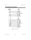
V.35 Technical Information
General V.35 Information
The ViewStation is designed to be compatible with tested network
equipment without any modification from the user. If your network
equipment varies from conventional V.35 video implementations,
you can adjust the operation of the signals. Use the following
technical information with information provided by your network
equipment vendor to customize your V.35 interface.
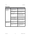
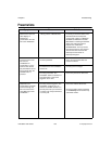
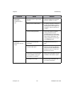
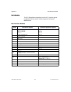
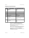
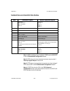
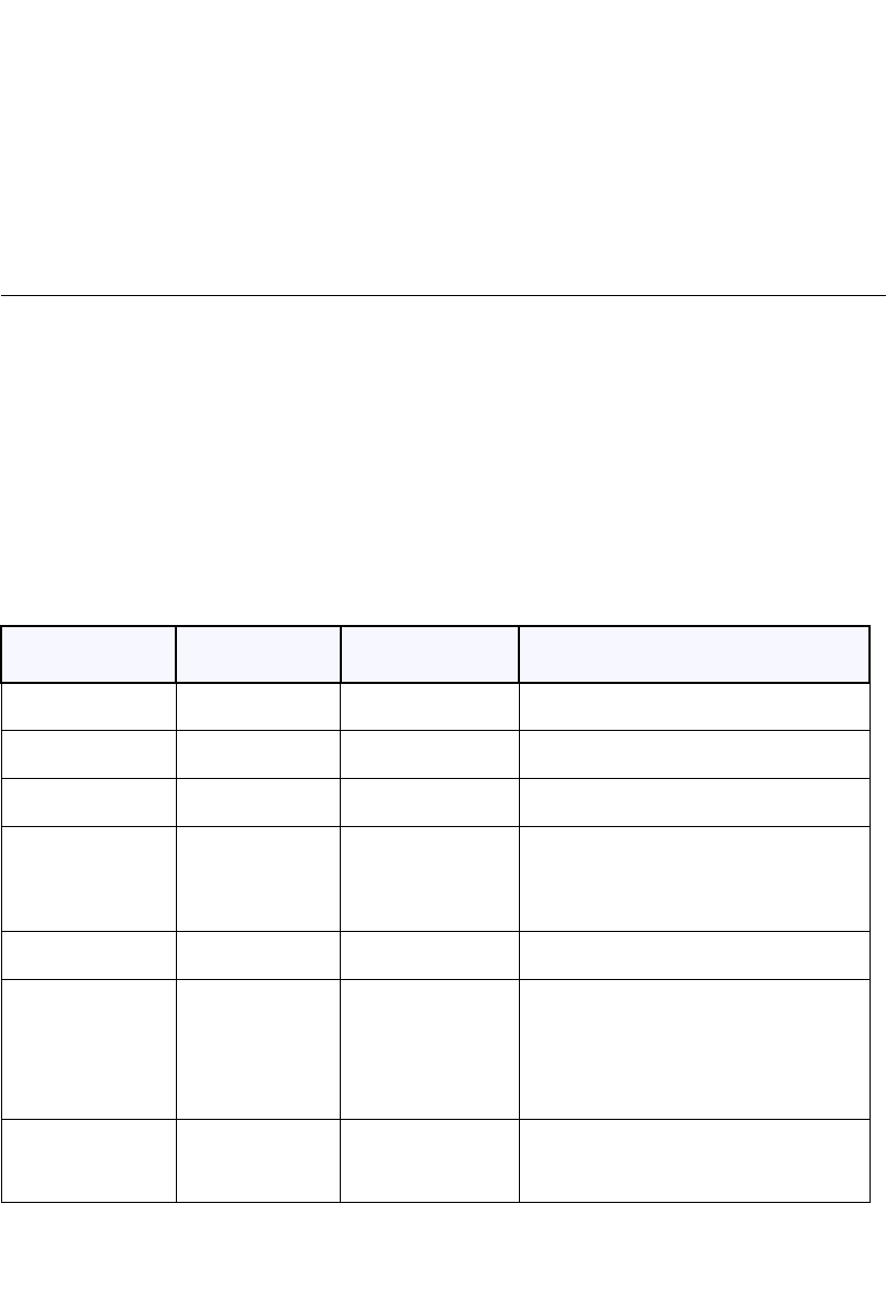
Serial Interface Control Signals
The following table describes the configuration of each signal.
Signal
(Cable Pin)
Direction Description Configuration Option
ST (TC/TT) OUT Send Timing
(clock)
Normal: falling edge sends data
Inverted: rising edge sends data
RT (RC) IN Receive Timing
(clock)
Normal: rising edge receives data
Inverted: falling edge receives data
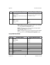
RTS (RTS) OUT Request To Send Normal: high voltage is logic 1
Inverted: low voltage is logic 1
DCD (DCD) IN Data Carrier
Detect
Normal: high voltage is logic 1
Inverted: low voltage is logic 1
Filter: allow DCD to drop for 60 seconds
before changing call state
CTS (CTS) IN Clear To Send Normal: high voltage is logic 1
Inverted: low voltage is logic 1
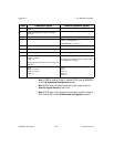
DTR (DTR) OUT Data Terminal
Ready
Normal: high voltage is logic 1
Inverted: low voltage is logic 1
On: constant high voltage
Note: if set to ON, inverted is not an
option.
DSR (DSR) IN Data Set Ready Normal: high voltage is logic 1
Inverted: low voltage is logic 1
Answer: Use DSR as a Ring-In indicator