


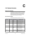

Appendix C V.35 Technical Information
© Polycom, Inc. 195 ViewStation User Guide
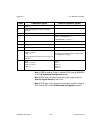
Note 1: DSR is used as a ring-in indicate if DSR is set to ANSWER
in the V.35 Advanced Configuration screen.
Note 2: RTS does not act as shown but act as a resync-pulse if
Security/Crypto-Resync is set to ON.
Note 3: DTR does not act as shown but remains at a high voltage if
DTR is set to ON in the V.35 Advanced Configuration screen.
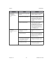
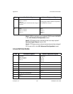
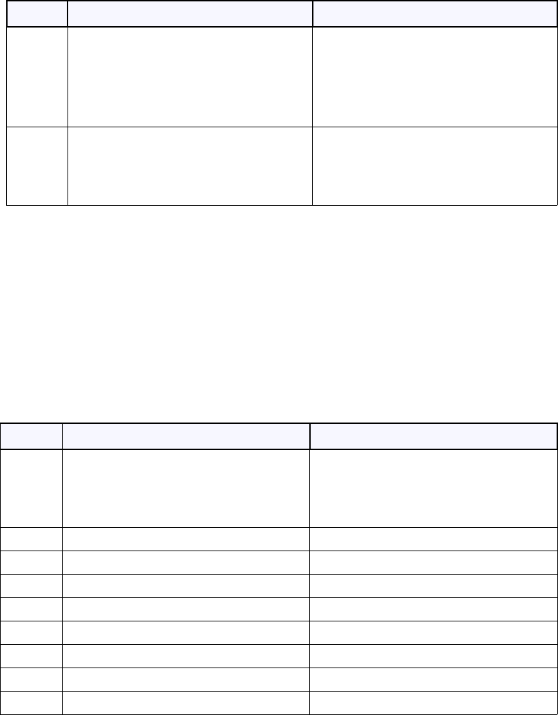
In-bound Call State Machine
State ViewStation Signals Network Equipment Signals
15 RTS = 0 <note 2>
DTR = 0 <note 3>
CRQ = 0
All signals go low if Far End or User hang-up is
detected.
DSR = 1 to 0, OR DCD = 1 to 0
A falling edge on DSR or DCD is interpreted by
the VS4000 as a hang-up.
16 IDLE
DTR = 0 <note 3>
RTS = 0 <note 2>
CRQ = 0
IDLE
RI = 0
DLO = 0
ACR = 0
DSR = 0
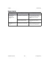
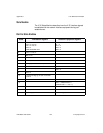
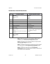
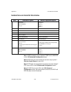
State ViewStation Signals Network Equipment Signals
1 Initial State:
DTR = 0 <note 3>
RTS = 0 <note 2>
CRQ = 0
Initial State:
RI = 0
DLO = 0
ACR = 0
DSR = 0
USER INITIATES CALL
2 DTR = 1<note 3>
3 Wait 10 ms
4 CRQ = 1
5 PND = 1
6 Set Digit (NB1,NB2,NB3,NB4)
7 DPR = 1
8 PND = 0